I’ve taken the plunge and dipped my toe into the CMOS world. Since I didn’t have any OSC experience I chatted with DSW (has a QHY186c) and decided on the QHY286C. This I purchased from Bern at ModernAstronomy who has always provided excellent service.
The issue with APS-C sensors when coupled with the Takahashi FSQ85 is that the edges start to show signs of star elongation, I already see this on my Atik460. This can be corrected with the FSQ-85 flattener (ordered from FirstLightOptics) which has the effect of slightly increasing the focal length but also reduces the back focus from the native 197.5mm to 56mm.
Effective Focal Length
455mm (f/5.4)
Image Circle Diameter
44mm
Metal Back Focus
56mm
FSQ-85 EDX with Flattener 1.01x
This means that I can’t use my existing Atik OAG->Atik EFW2 and Atik460 because it’s total distance is 59mm (22mm+24mm+13mm) so it’s out by 2mm even once you include the filter effect on the back focus. Note – This is also true for my Starlight Xpress configuration.
I do not understand why Atik could not have got to within the 55-56mm range by shaving off a mm here and there 🙁 I may need to replace all Atik gear when I convert to mono CMOS or replace the OAG with a guide scope.
So onto the QHY268C, the OSC CMOS unfortunately has a CAA tilt adapter instead of a direct thread connection. This wastes 11mm of precious back focus giving a total distance of 23.5mm whereas the recently released QHY286M CMOS has a 12.5mm back focus !!!!
Also the QHY268C does not have an IR/UV cut filter in place so you need to buy an additional filter and holder and add that to the cost and factor in the adapter and distance needed …. I’m starting to regret this purchase more and more !
Source – QHYCCD.com
Back to the Takahashi Flattener (TKA37852), the back focus is 56.2mm but we add on the filter thickness as it changes the light path (2mm/3=0.66mm) so ~57mm (56.9mm), the imaging train is as follows :
Adapter
Distance (mm)
Accumulated Distance (mm)
Connector
OU031
2
2
M54(M) -> M54(M)
QHY 020770
4
6
M54(F)
QHY Spacers
14.4
20.4
screw
QHY OAG-M
10
30.4
screw
QHY 020055
2.5
32.9
screw
inc filter
0.6
33.5
–
QHY CAA adapter
6
39.5
screw
QHY268C CMOS
17.5
57
screw
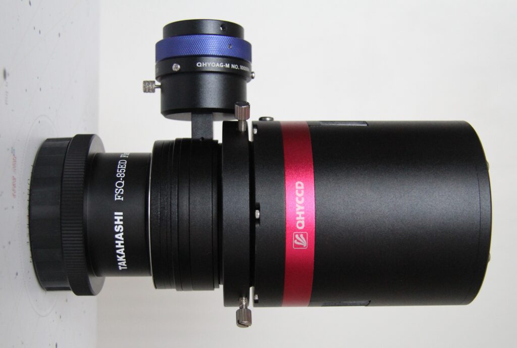
FSQ85 Flattener to QHY268C imaging train
The combined weight is 1365g so I may need to adjust the balance of the scope a little as it heavier than my Atik460/EFW2/OAG setup at 1080g.
Completed – Imaging train ready for first light
I may have to adjust the spacers a little but I won’t know until I have received a 2-inch Optolong L-Pro light pollution filter which is currently on back order from FLO.
Transmission chart for Optolong L-Pro
QHY268M
The recently released mono version of the QHY268 looks like it has a proper screw face plate with a more acceptable back focus of 12.5mm. This is more reasonable and would allow me to couple a filter wheel and OAG as well not requiring a IR/UV cut filter.
Like SyedT on StarGazersLounge I could go back to using a guide scope and ditch the OAG and then the imaging train could incorporate a rotator :
I was thinking of a rotator for the remote Esprit120 which has a generous back focus of 76mm so I should have no problems there but that will be another adventure for the future !
I thought I ought to document this so that I remember this is now the new normal for making a flat master for my CMOS camera, the ZWO ASI1600MM. The problem I found again after not processing images for some time, was that the normal way of processing without Flat Darks produces a master flat with embossed, so raised doughnuts across the image.
Batchpreprocessing – > Darks tab -> Optimization Threshold -> move from 3 to 10 – > this removes the dark entirely and also removes the amp glow but introduces loads of noise so clearly not right at all. So I contacted my friend Dave Boddington who is a bit of an expert on this topic and he gave me some good advice that has of course worked.
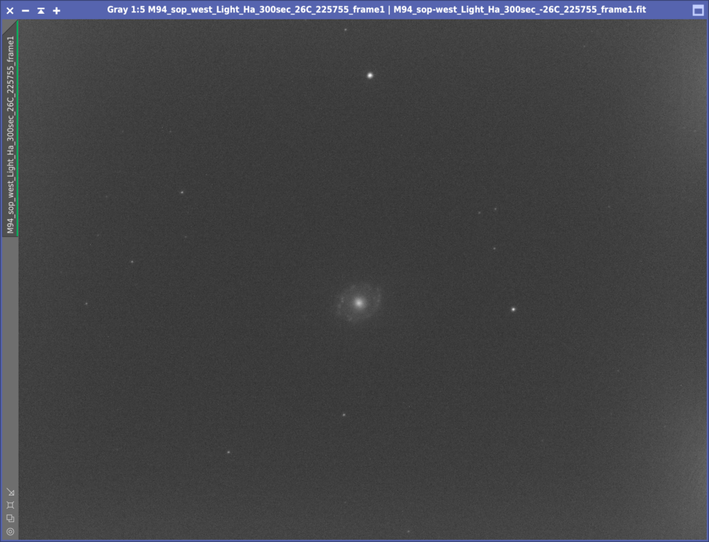
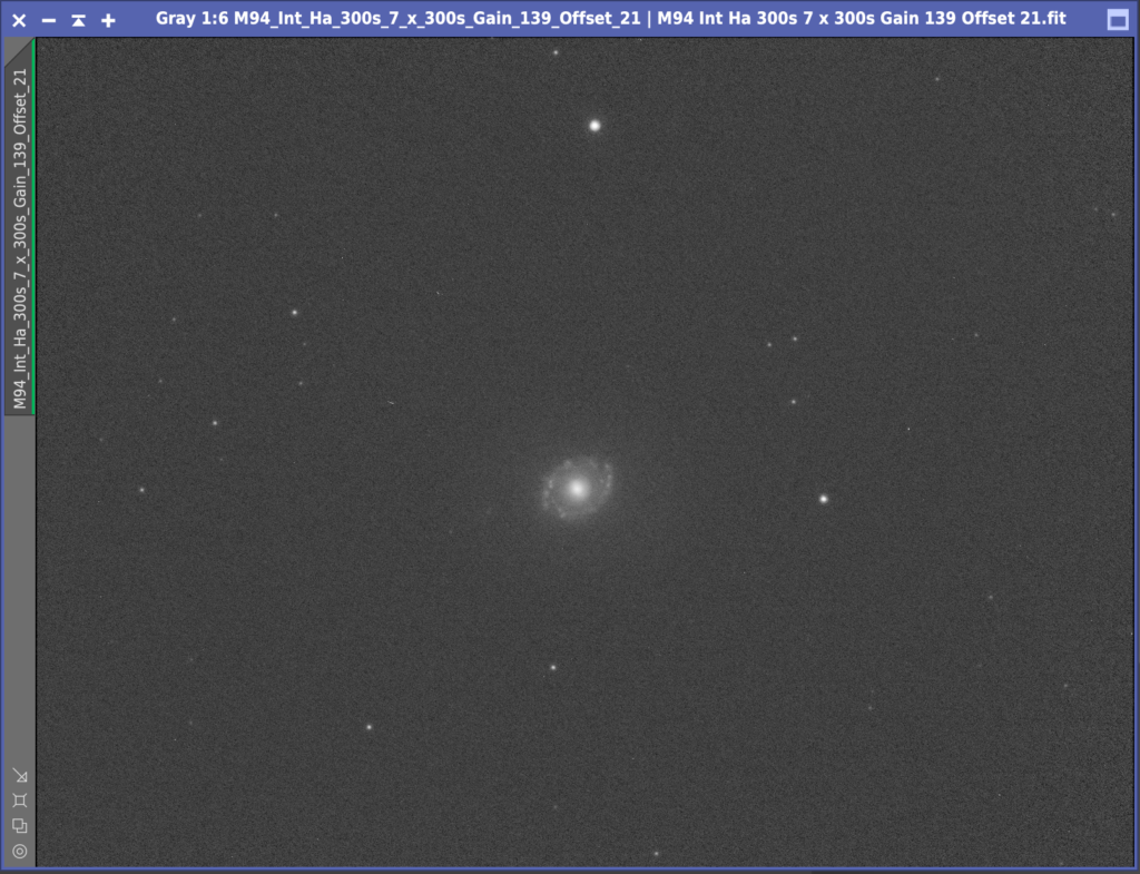
So first let’s detail what I am calibrating. On the 20th April 2020 I took a set go Ha frames of M84, these were 300s exposure and with a Gain of 193 and I believe an Offset of 21, however we had some changes over the previous week so driver the Offset is no longer stored in the FITS header. It was when we were using the ZWO native driver. The temperature of the cooler was set to -26℃. I have 8 of these frames.
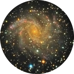
M94 300s light
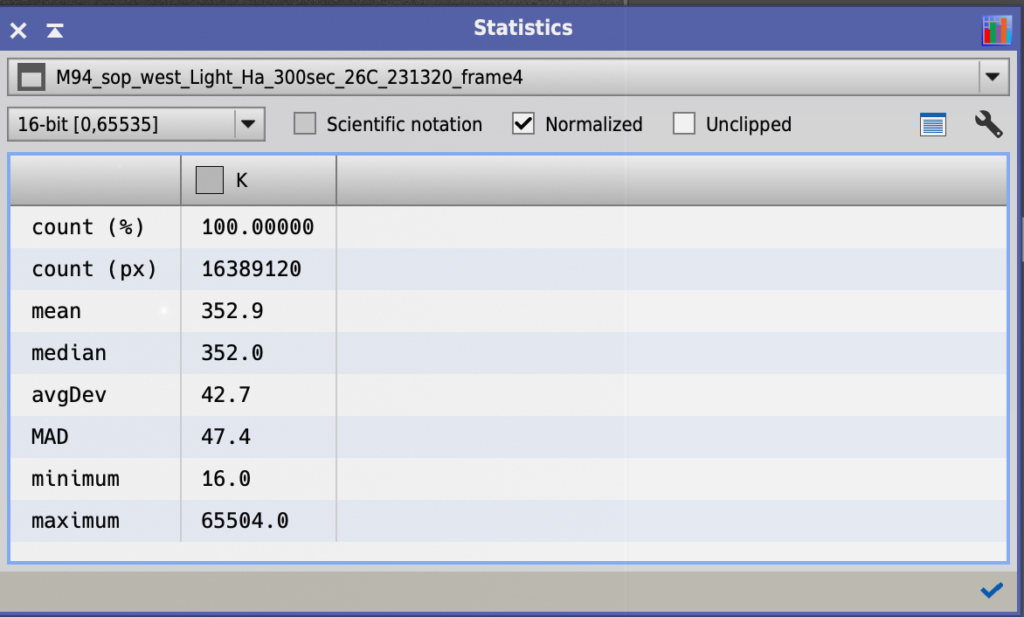
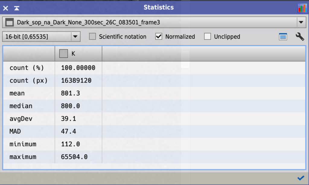
I also have a set of 10 darks at the same settings. However when using the Statistics tool Dave noticed the Mean of the image was 800 and the Mean of the Ha frame was 353. This is in a 16 bit notation. The camera however is a 12 bit camera and this means the Mean for the dark is 50 and the Mean for the Ha is 22, so a difference of 28 in 12 bit and 447 in 16 bit. I will come back to this later.
Mean of Ha 300s lightMean of Dark 300s
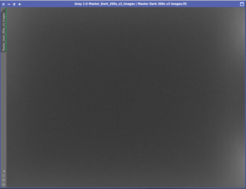
First I created a Master Dark for the Ha frames using the normal ImageIntegration settings. I did not calibrate darks with Bias as you do not need bias with a CMOS cooled camera. Next I created a Master Flat Dark for the Flat frames using the same ImageIntegration settings.
Single 300s Dark with hot pixels and amp glow
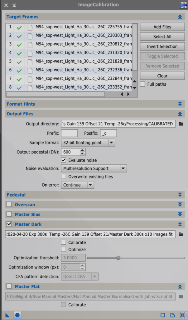
Then I found the Ha images did not need to have the flats applied so I skipped that step for the narrowband images. Next I Calibrated the Ha lights with ImageCalibration and because of that discrepancy above which looks like it was induced by having the Offset for the darks set to 12 and the Offset for the lights set to 21 I added 600 as suggested by Dave Boddington to the Output Pedestal in the Output files section of ImageCalibration. I made sure Evaluate Noise was ticked and that both Calibrate and Optimise were unticked in the Master Dark section. Master Bias was unticked and so was Master Flat for the narrow band images as mentioned.
Calibrating Ha lights with Master Dark
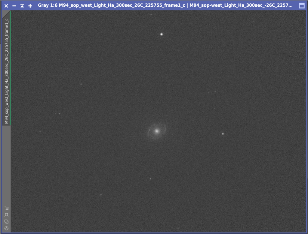
This created a clean set of calibrated Ha lights that did not require flats to be applied.
Calibrated 300s Ha light with Master Dark
Next I had some issues in Star Aligning the frames. The error I received was ‘Unable to find an initial set of putative star pair matches’, due to the frames being very sparsely filled with stars and the background being quite light compared to the stars. A quick look on the PI forum showed increasing the Noise Reduction in the Star Detection section from 0 to 4 sorted the issue, with all but 1 frame being aligned. I was then down to 7 x 300s Ha lights. The final frame was very light due to cloud.
7 x 300s Ha Calibrated with Darks, Aligned and stacked
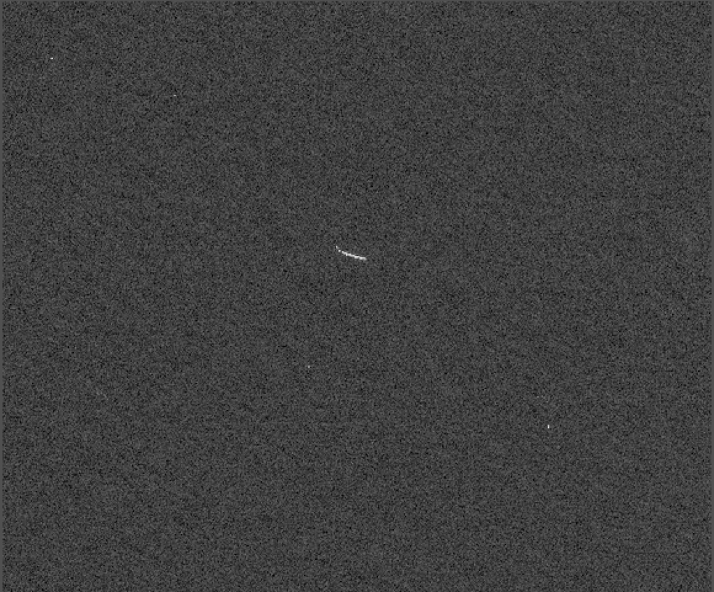
I then integrated these 7 frames together. I had a challenge with trying to get the hot pixels in a few areas to disappear using Cosmetic Correction and pixel rejection during stacking so I will remove these after by hand before combining into the larger set
hot pixels not removed
So in essence what I have learnt is that I need to have really clean filters and camera glass. That all the doughnuts are on the those surfaces and not anywhere else. That the flats must be between 22k and 26k for the CMOS cameras, although this has some tolerance either way. That I need to set the camera to the right Gain, Offset and Temp as the lights and that I need the right flats for the right lights!
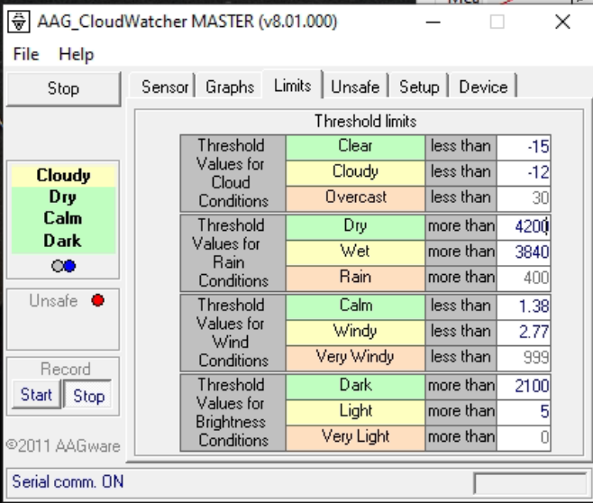
Opened dome early switching the safety for the brightness on the new AAG. The first thing to do tonight was to calibrate a little but more the infrared sensor which informs the cloud coverage. This was suggesting it was Cloudy, borderline Overcast and given it was very clear with a hint at wisps of cloud I adjusted the couple of figures for the sensor, from -17 for Clear to -14 and from -14 for Cloudy to -12.
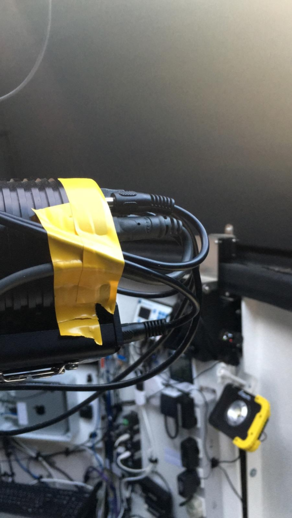
I then set about taping up the USB and power for the SX camera on the Esprit. This is because the connectors supplied are clearly not in tolerance as I have tried many cables and they call fall out. The tape should suffice for the moment and now the camera reconnects to the NUC computer running SGPro.
Tape for USB cable
GingerGeek and I started to have a look at the sky around 9pm. The sky was not totally clear with some wisps of cloud. We tried to get to a point where we could test guiding the 12″ through the Esprit, however as ever the clouds rolled in. However, during setting up the SX814 camera on the Esprit as the guider and performing a darks calibration run we got an error on the USB bus again (we get lots of USB errors) which not only kicked out the SX814 but also the AAG weather station. The problem was it almost killed the AAG software and we had to cancel the process running to resolve. This meant we lost all the settings in the AAG so we have tried to rebuild as per the new screen shots below.
AAG Weather Station New Settings
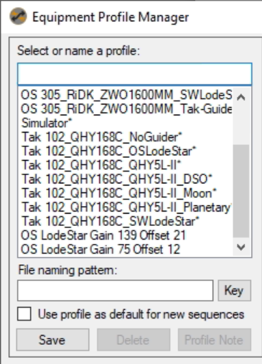
So instead we re-ran the Flats Calibration Wizard for the OS with the camera set to Gain 139 Offset 21 and also another run at Gain 75 Offset 12. The reason for re-running is that I suspect the flats we have are ever so slightly over exposed at 30-32k rather I prefer them to be at 22-23k.
We also created 2 new profiles that were simply named so we can see them in the list and simplify the naming convention and amount of profiles needed. We will choose the guider on the night within one of the two profiles created. We will also look to review and simply the other profiles for the two additional OTAs tomorrow and delete the remains profiles given the large number we now have.
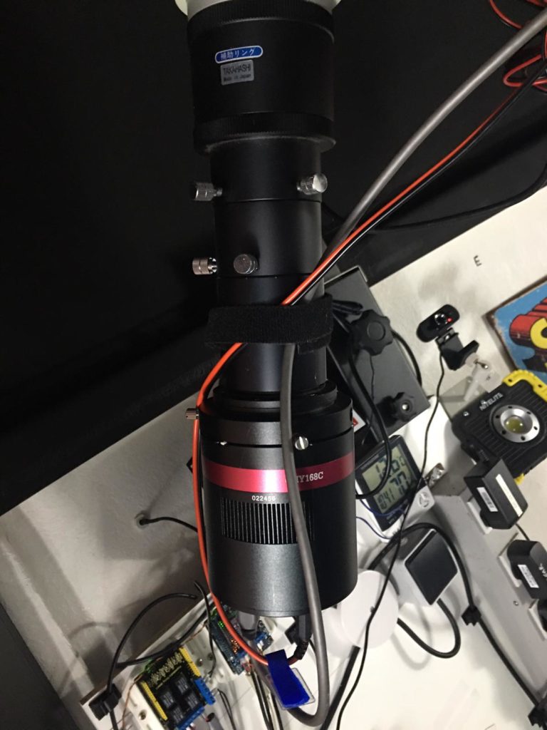
Bob had noticed a lot of dirt on or near the sensor on the QHY168C camera that forms part of the imaging train on the Tak FS102. Today I took the camera off for a little spring clean.
The first thing was to mark the rotation angle of the camera so that it goes back on exactly. 21 degrees is the rotation angle as measured through an actual image.
Taping up position angle on QHY camera
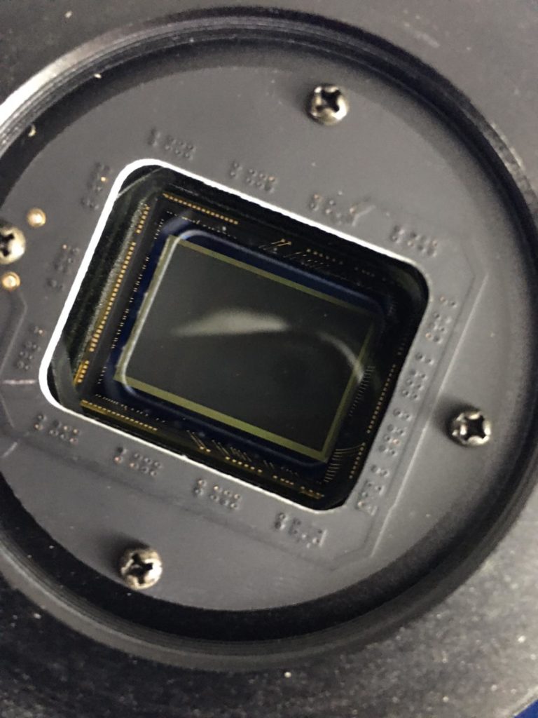
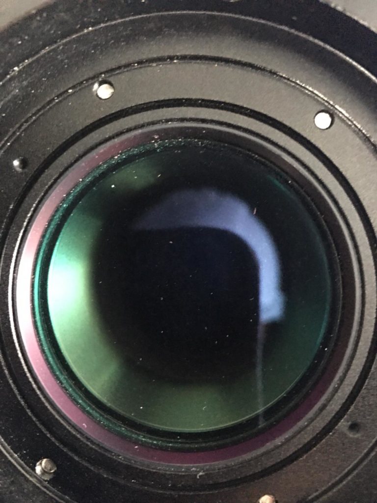
Next I took the camera off loosing the 3 screws holding it in position and then took a look at the CMOS chop glass cover for dirt.
Inspecting QHY168C for dirt on glass cover
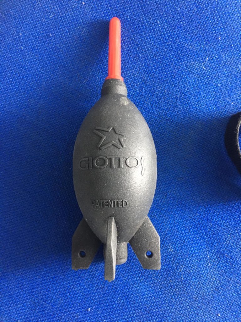
There was really only a couple of pieces of dirt on the cover so I removed them with the blower.
Rocket blower
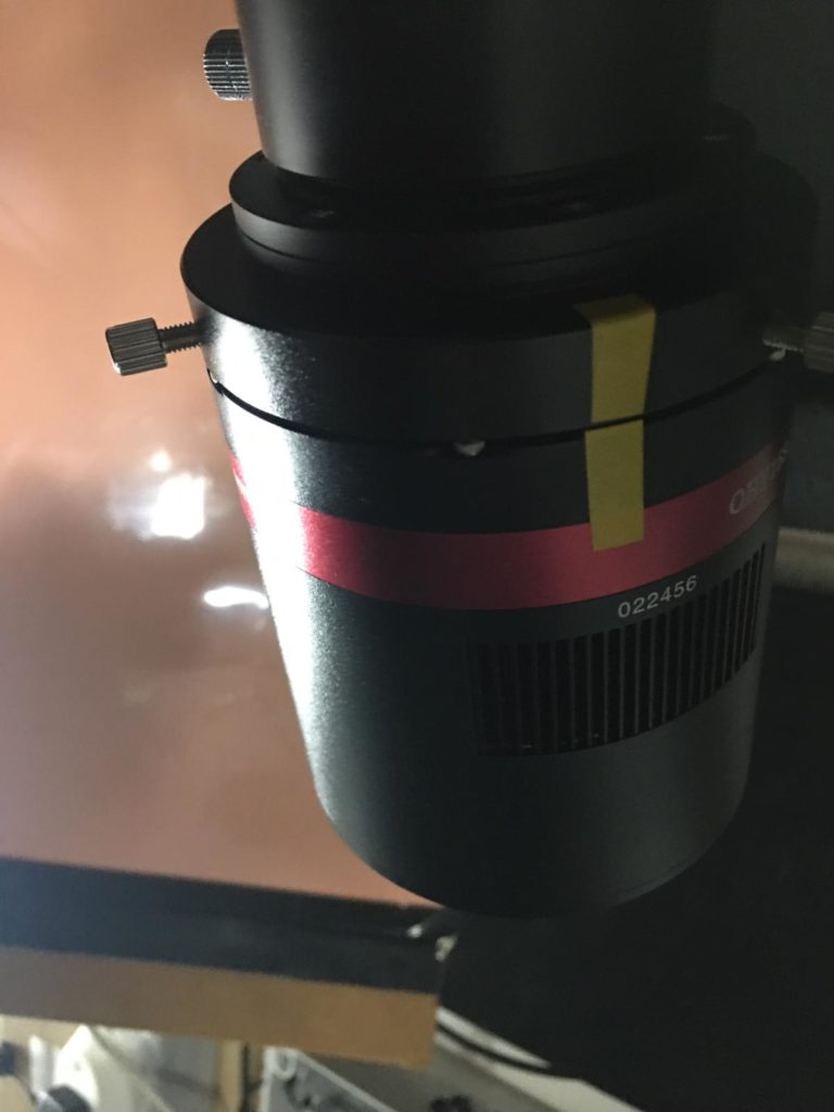
Next I took off the extension tube with which has the glass UV lens inside. At this point I forgot to mark up the position angle when I took the extension tube off. So when I reattached I look at the image train photo to adjust. Hopefully it will be very close and will only require minor adjustment.
Tak FS102 QHY168C imaging train
Looking at the UV filter it was instantly visible that there was plenty of dirt and dirt on the glass lens, however it transpired to be on the inside of the lens toward the OTA. O removed the filter to clean with the rocket blower.
UV glass filter dirt and dust
I then reattached the filter, the camera and reset the angle. I followed up by feeling for any play in the Tak OTA bracket that piggy backs it on the OS12″ OTA. I could not feel any. I was checking due to a shift on the FoV when Bob was recently imaging. Again the next time out we will need to readjust.
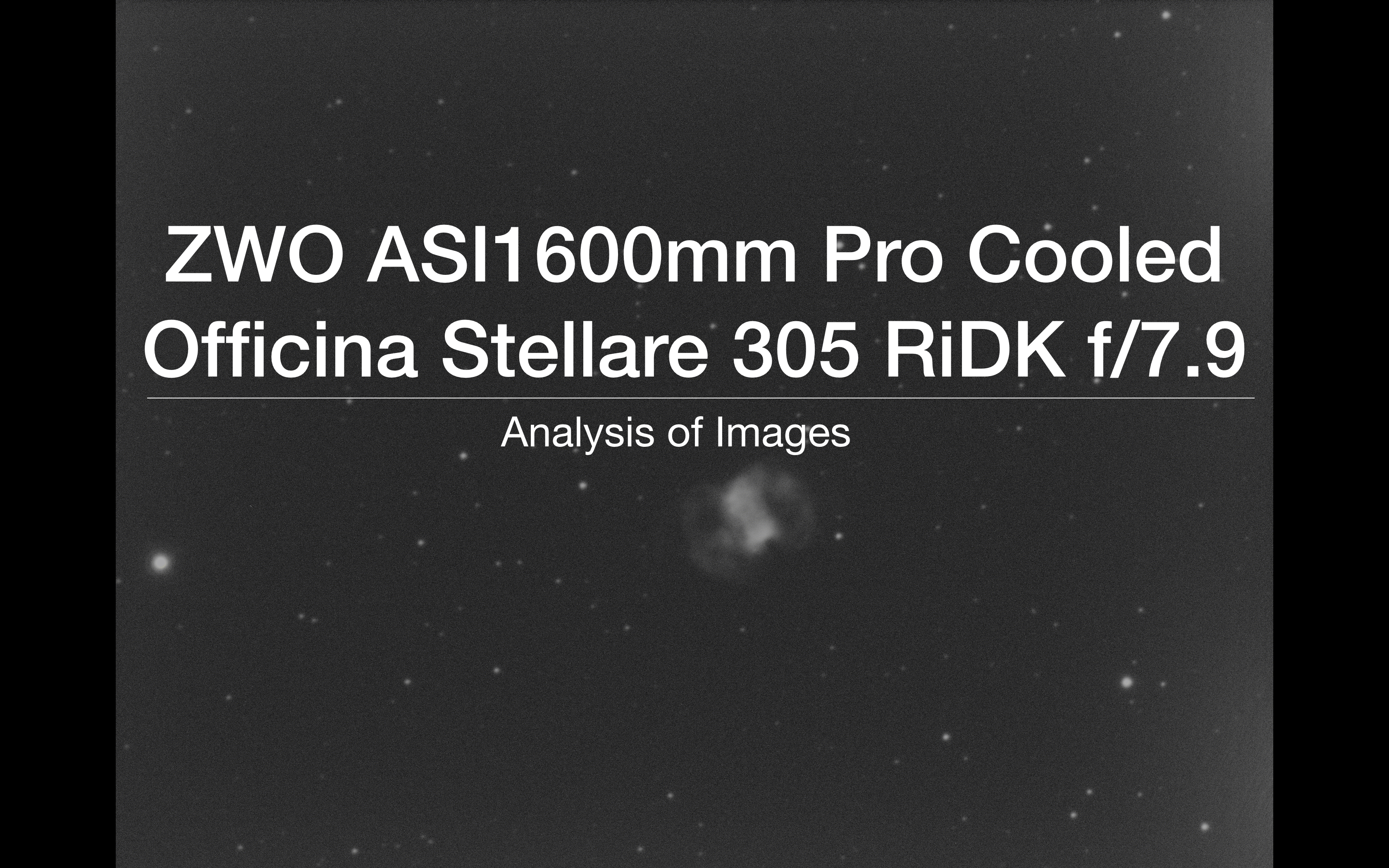
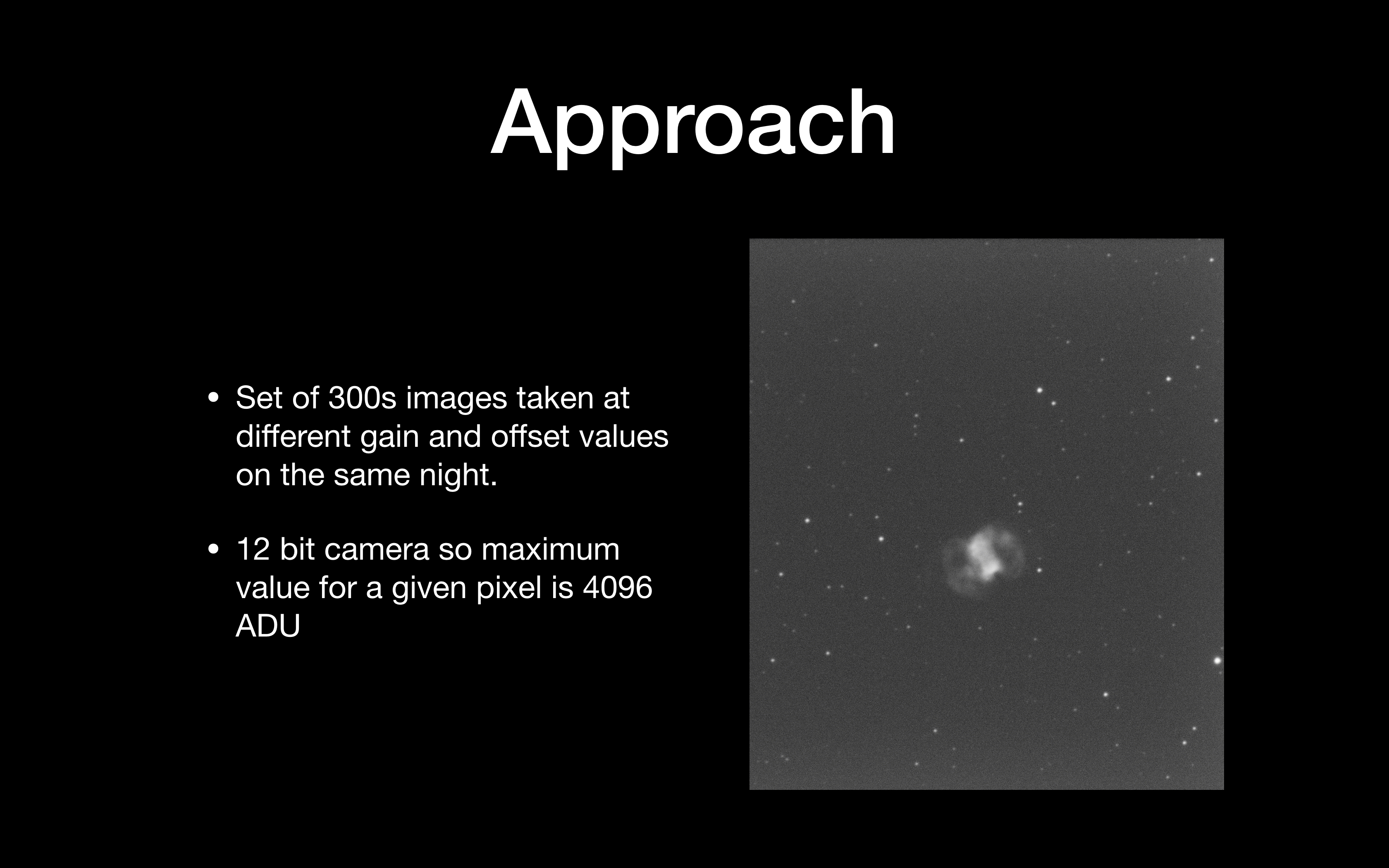
So the main approach here was to start testing the ZWO ASI1600mm on 5min images and decide which is the best Gain and Offset to use. As the object is a planetary nebula I have used my Astrodon 5nm OIII filter to bring out the faintest parts of the nebula. To be thorough, and this will take time, I plan on running the tests for all 7 filters I have.
I have done extensive reading on the topic of image analysis and hope to apply here what I have learnt. Given then camera is running 12 bit, I have a maximum pixel value of 4096 which represents saturation and then any further response is non-linear. Once I have completed 5min testing I will try for 10, 15 and 20 mins. I will then perform further testing by taking a sample set of 10 images to stack and see how that compares with similar total exposure times across the frames.
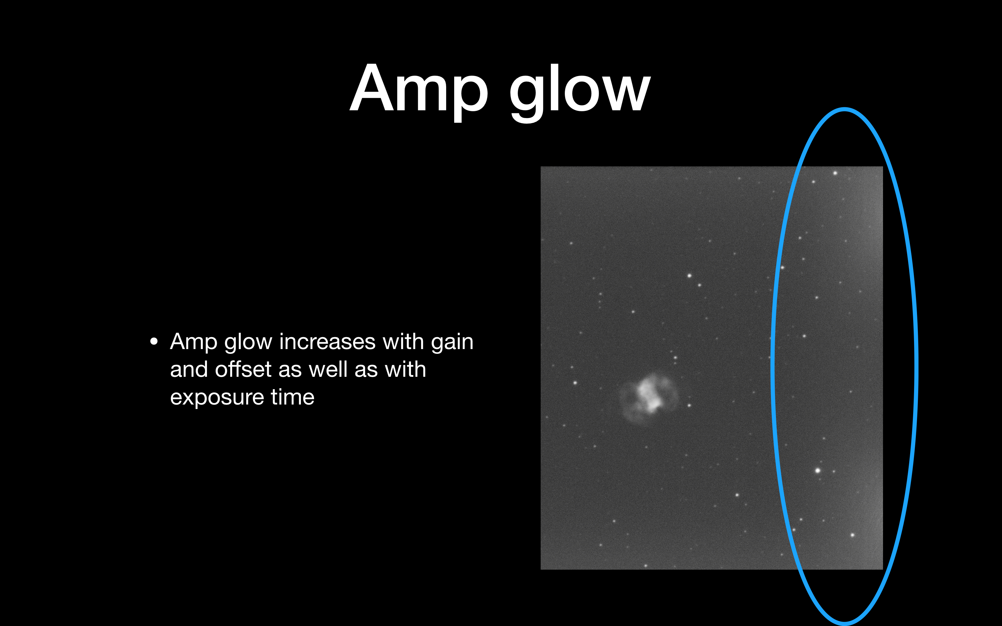
Amp glow is a particular problem with CMOS. Despite the ZWO site suggesting that amp glow is virtually removed in the Pro Cooled camera, it is clearly not, as can be seen in single 5 min subs. The good thing is a dark will remove it effectively. What I need to make sure is that the amount glow does not swamp the image so much that it overpowers the signal from the faint nebula.
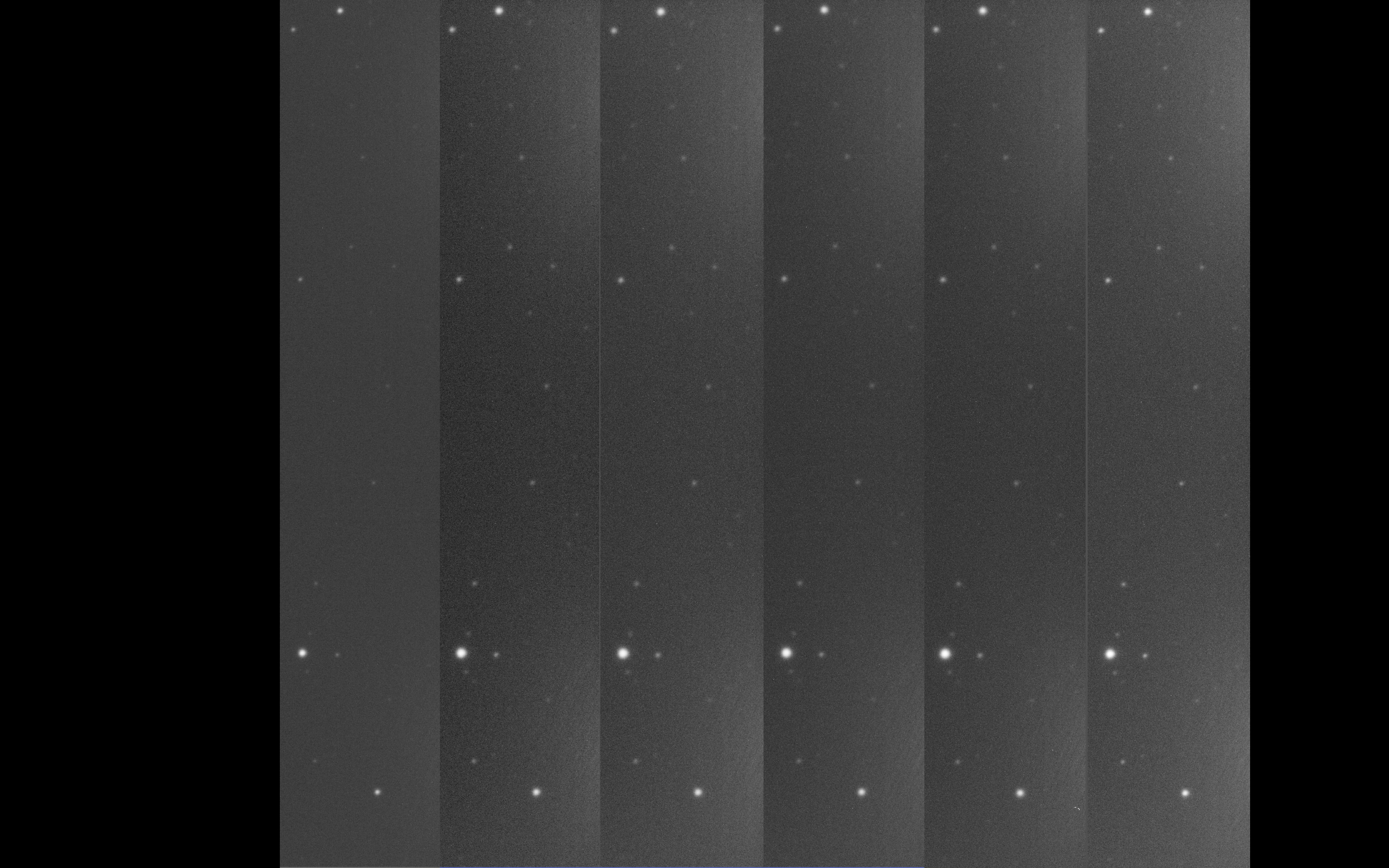
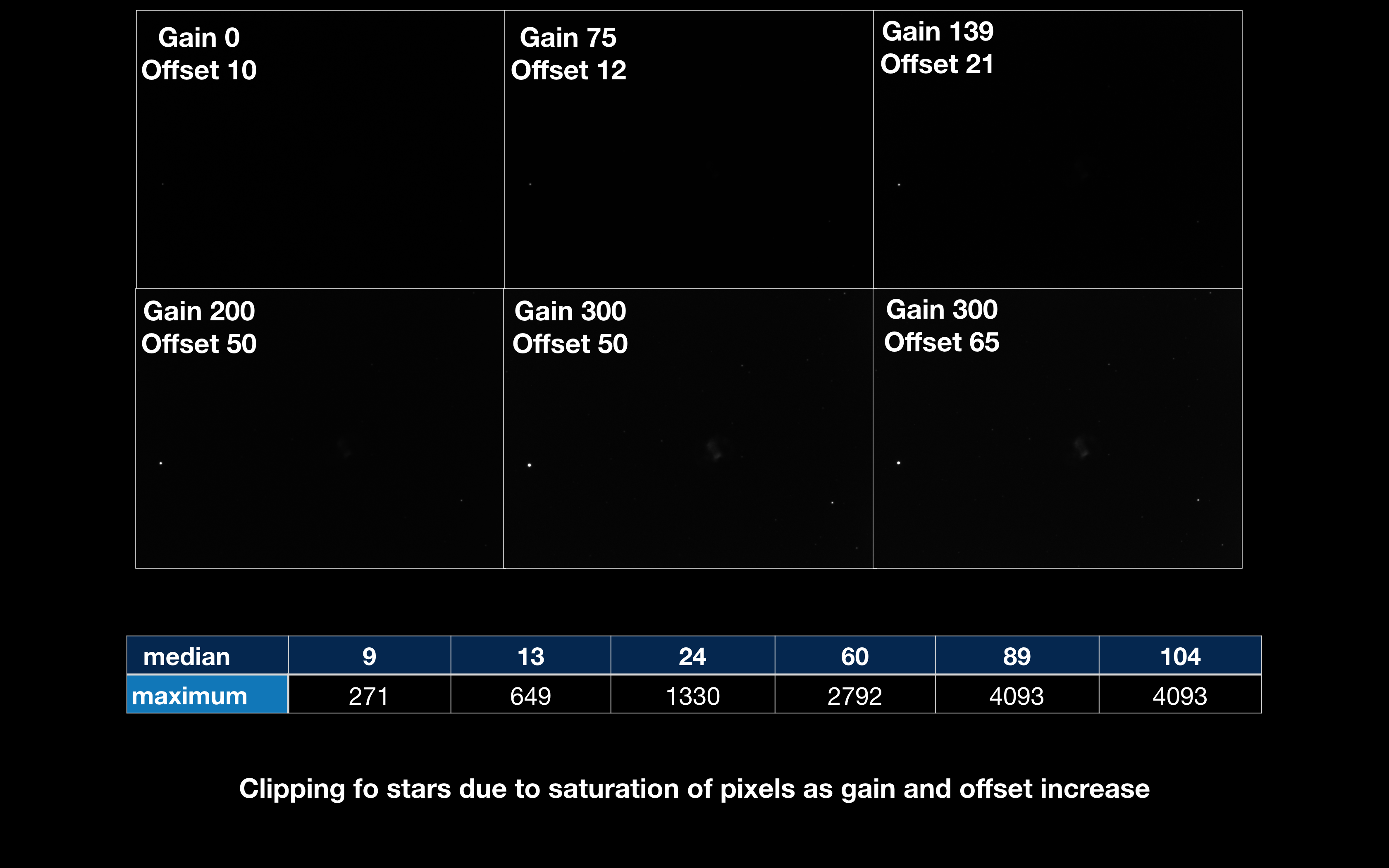
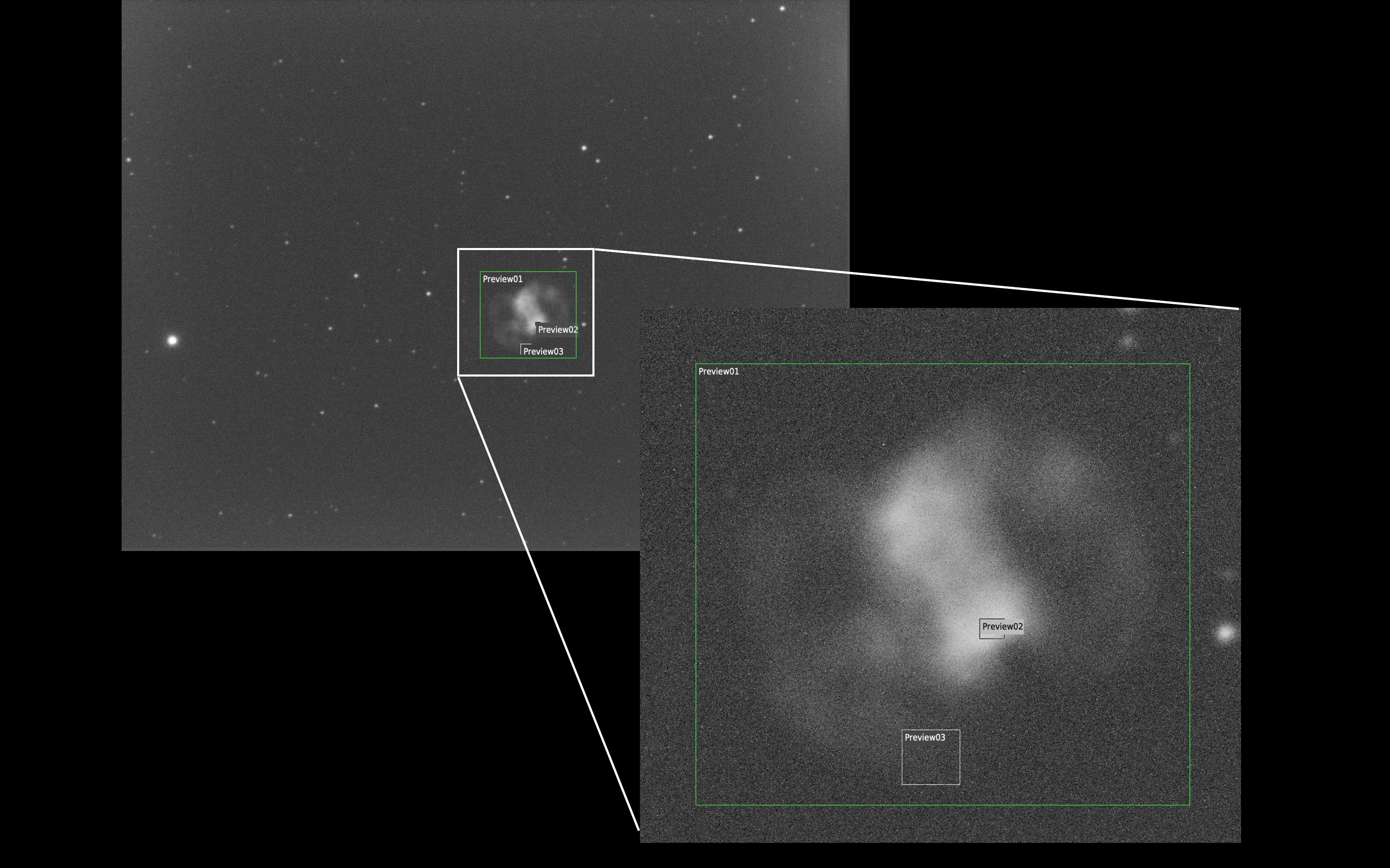
Increasing the gain and offset value from left to right you can see a marked increase in the amp glow. The image slices below are taken from the far right of each frame.
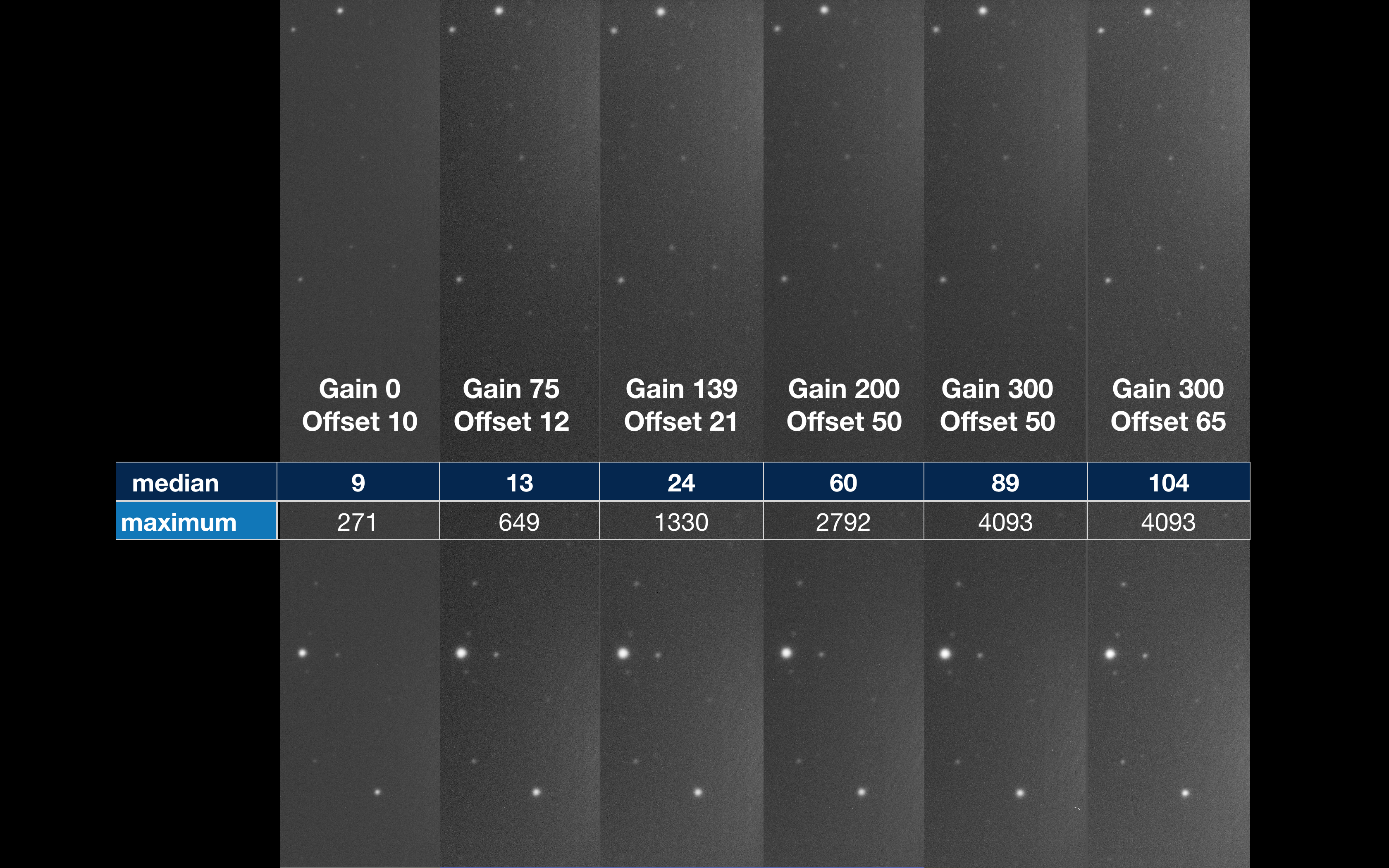
The offset figures in relation to the gain figures have been taken from my reading of various material. The median values are that of the background and the maximum values that of the stars. You can see on this 5min exposure that by the time I reached a gain of 300 one or more of the stars are saturated. In fact the brightest star in this slice is SAO 22510 which is mag 9.53.
Another way to visualise the saturation effect is looking at the raw unstretched image, whilst a star is visible in the image using gain 139 and 200, on close inspection within PI and looking at the values of the pixels of the star they are not saturated. However gain 300 is. The purpose of this is that an unstretched image is not the defect for telling if parts of the image are saturated as some texts describe, but one can see the increased brightening of the star by gain 300 to know it is a problem.
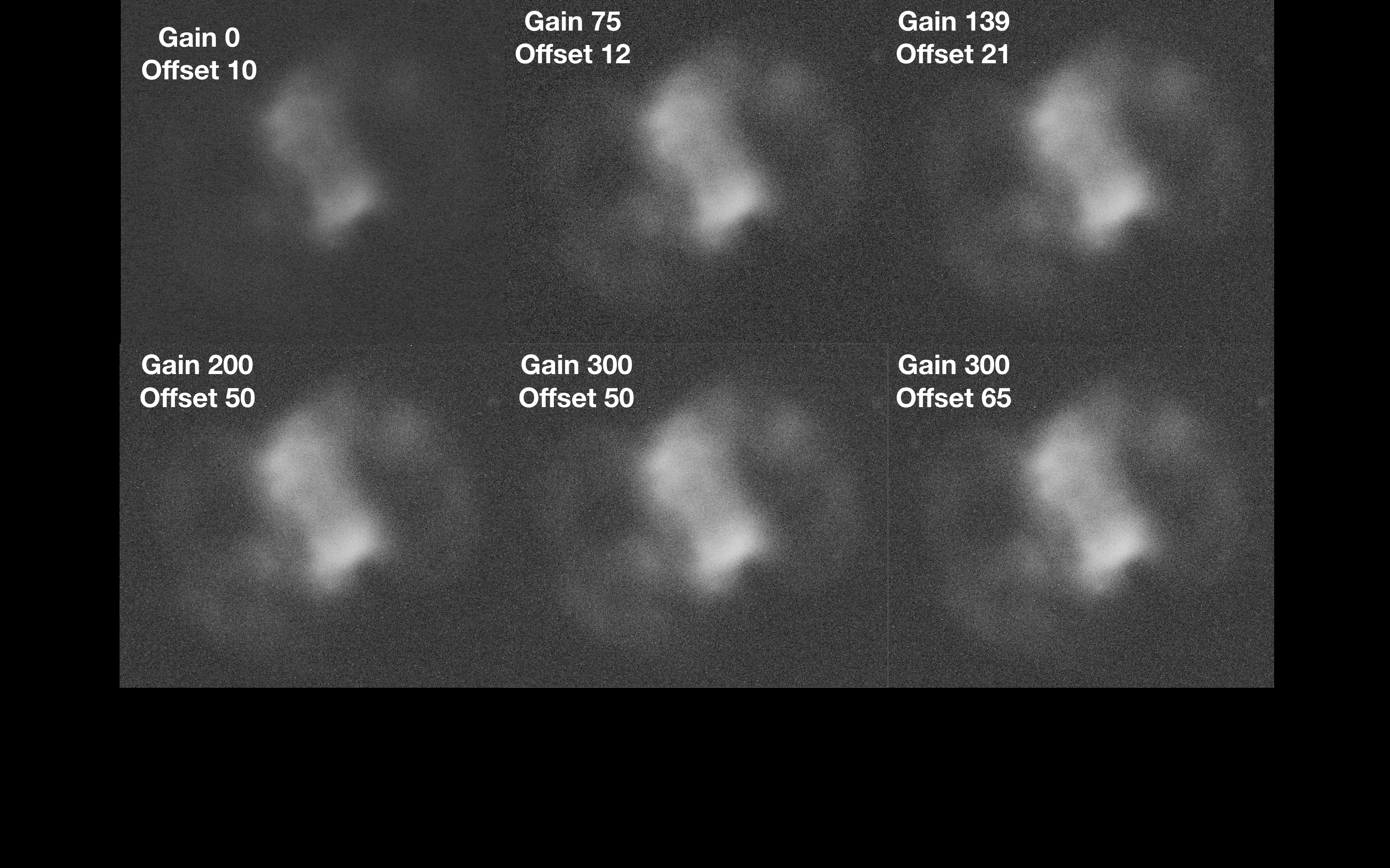
So whilst I have seen the clipping a a few stars at the highest gain I have tested, what about the planetary nebula itself? From the below stretched image one could assume that the brightest part of the nebula was fairly bright and heading towards saturation, but don’t be fooled! Also there is a noticeable increase in the background brightness as the gain increases.
Again as for the amp glow, the aim is to balance the ability to amplify the faintest parts of the nebula without swamping them with the background brightness.
Again here are the values of the settings for gain and offset against the central section of the image.
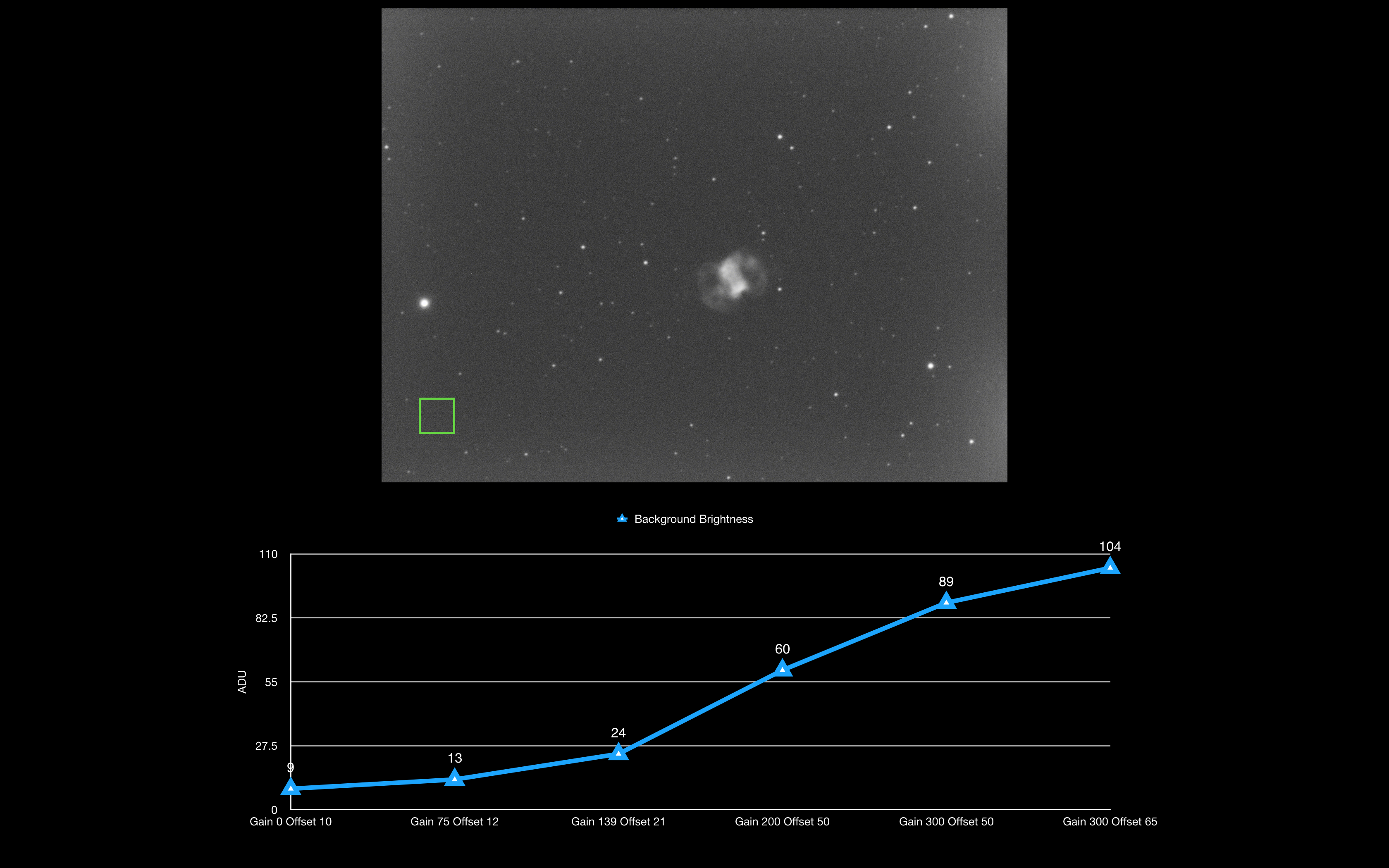
So how bright did the background get? The graph below shows a section of the background free from stars and charts the increase of brightness from a mean figure of 9 ADU with the gain set to 0 and a mean figure of 104 with the gain set to 300. So a large increase but but at least up until gain 200 not a problem, as we will see when we look at the faintest part of the nebula later.
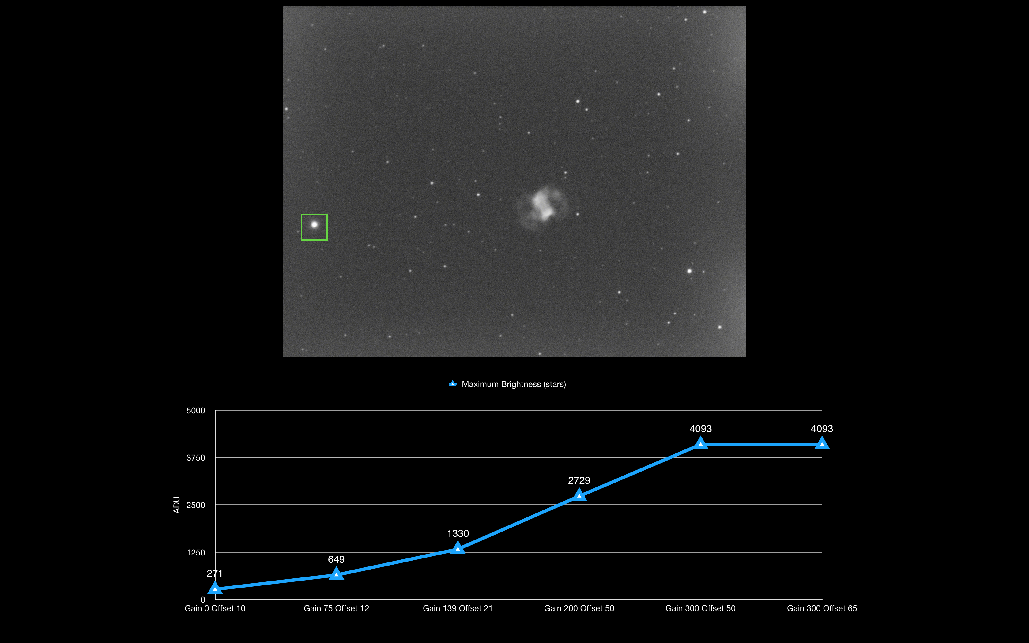
This graph looks at the bright star SAO 22551 (HIP 8063) which is mag 6.66 and the brightest star in the image. Again as previously seen in the right hand slice of the image the star is saturated by gain 300. All figures are the maximum pixel values.
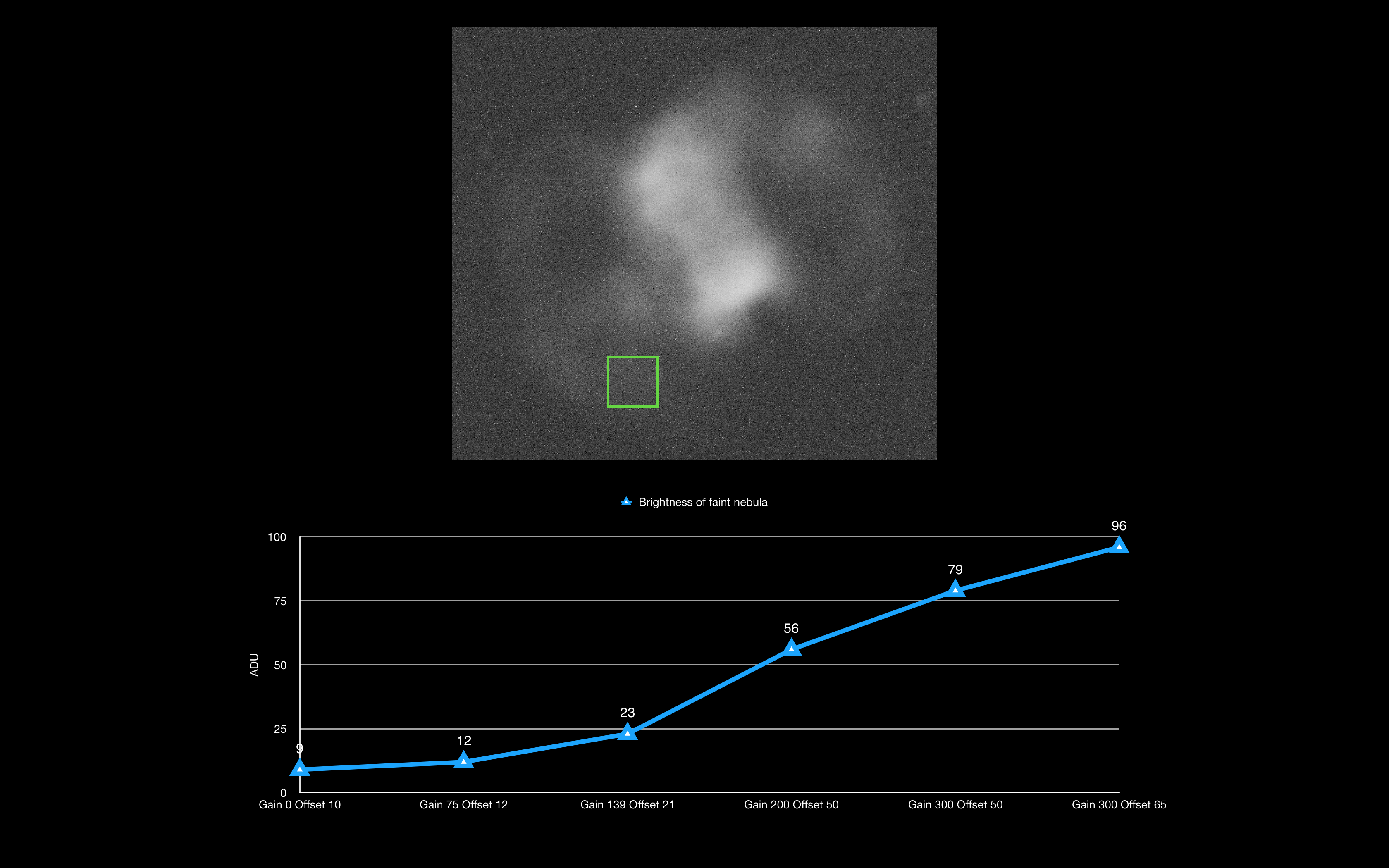
Now let’s focus on the nebula itself and go back to using the mean ADU figures. The picture below shows the section of the nebula I will use for analysis. In particular I focused in on the brightest lobe of the central portion of the planetary nebula and the faintest portion of the left arc.
So looking at the faintest nebula within the left arc we can see that it is not very bright at all and the brightest it gets at gain 300 and offset 65 has a mean figure of 96 ADU. Each and every image at the different gain setting and offset setting is seemingly just below that of the background, which in itself is interesting as the nebula seems to be fainter than the background. So more analysis was needed.
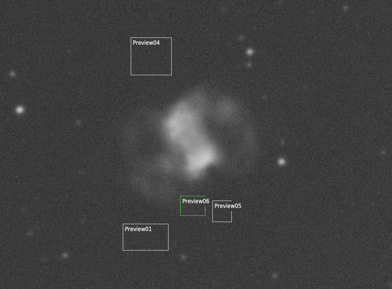
However I then went back and looked at a selection of areas of the background across the image to find that the original background selection to the bottom left of the image was brighter than other areas. Below you can see the image of gain 200 and offset 50, this time with 5 selection boxes. Preview 6 is the nebula as recorded before is mean 56 ADU. Preview 5, so the sky right next door to it has a mean figure of 55, so just below the nebula, hence it is only barely visible. Preview 1 is 54 ADU and Preview 4 is also 54 ADU. So there is brightening on that bottom left corner of the image, so had the nebula fallen at that spot then it would be swapped by the background.
There is only 1 ADU between the nebula and the background adjacent to it at gain 200 offset 50. If we looked at the same to regions in the image of gain 300 and offset 50 then you get a 2 ADU difference. The image with gain 300 and offset 65 gives a 3 ADU difference. So the results show that both gain and offset both help increase the contrast between the background sky and the faintest part of the nebula.
Various previews can be seen to analyse the background vs nebula brightness
The final image below shows the brightest part of the nebula. At gain 300 and offset 65 you see a mean value of 544 ADU which compares to 96 ADU for the faintest part of the nebula and an adjacent background of 93 ADU.
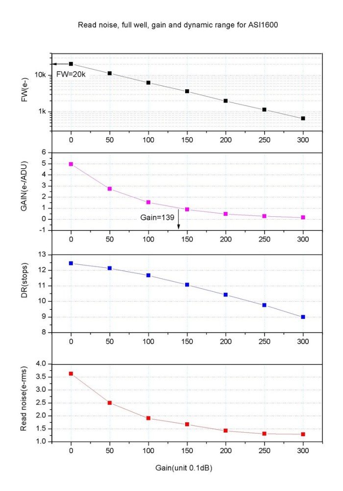
The final piece of information pertains to the camera/chip specification and performance. The graphs below are from the ZWO website and clearly show as expected the more you increase the gain the read noise is lowered but unfortunately so is the full well maximum (the amount of electrons you can store in a pixel) and the lower the dynamic range, which for deep sky objects is a required.
So from this first piece of testing what have we learnt? Whilst there seems to be a good sense for increasing the gain and offset to help with the SNR especially between the background and the faintest part of the nebula, the increase in amp glow, decrease in dynamic range and reduction in the well count are all factors. Stacking as we will see, will undoubtably help the situation without necessarily setting a high gain. You can see why people say use Unity Gain, so the setting where 1 electron on the sensor = 1 ADU potentially gives the best result from a tradeoff point of view.
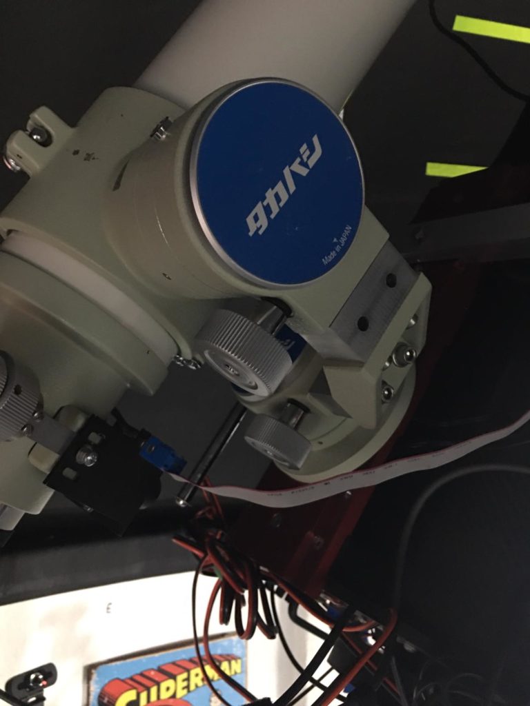
I have spend over 4 hours today reading about the Gain and Offset settings for the ZWO ASI1600mm Pro Cooled mono CMOS camera I have on the back of the 12″ Officina Stellare 305 RiDK f/7/9 telescope.
ZWO ASI1600mm Pro Cooled on Officina Stellare 305 RiDK
In particular the posts by Jon Rista and the images with a similar setup from Glen Newell have led me to a handful of setting I will now try from my location and on M76, the Little Dumbbell planetary nebula that I had started to image recently. I must also comment that Kayron Mercieca also had some useful information pertaining to testing your camera and OTA imaging train for exposure times. See link here
Discussion on exposure times and setting – Cloud Nights
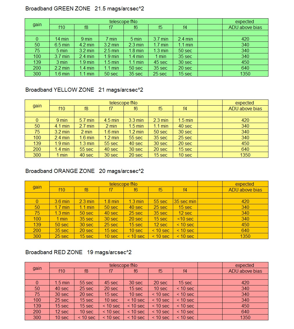
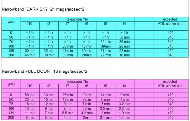
So I have already taken a set of images on the 8th October, 14 of them and they were at a Gain and Offset of 10 (I believe these settings are less than perfect) and an exposure of 1200s, so 20mins through an Astrodon OIII narrowband filter. My location is on a good night in the Orange Zone as per the charts borrowed from the forum discussions and when referring to broadband imaging. For narrow band as per my test here I am between the purple and blue zones.
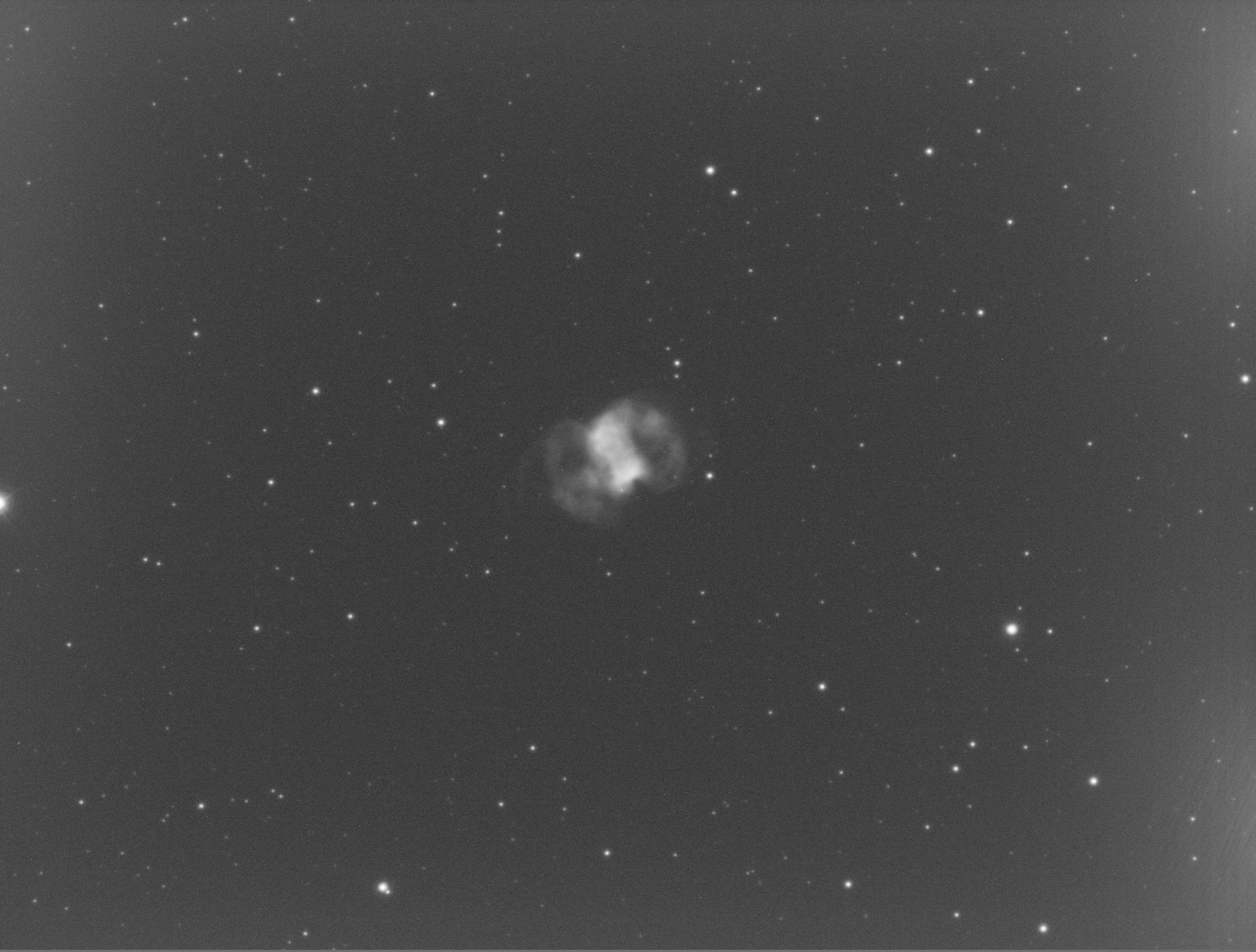
Inspecting the original frames I took you can see slight amp glow from the right of the image, the background has a median of 10 ADU at 12bits. None of the stars are saturated or clipped. The brightest star is 1,854 ADU our of a dynamic range of 0-4,095 ADU. The faintest nebula I can see is 11 ADU so just above the background and the brightest part of the nebula is 77 ADU.
M76 – 1 x 20min OIII Gain 10 Offset 10 – ASI1600mm Pro Cooled
So I will attempt to take a set of images at the following settings across 4 exposure times of 300s, 600s, 900s and 1200s at or after astronomical night at 20:56 onwards if the clouds hold off.
Gain 0 – Offset 10
Gain 75 – Offset 12
Gain 139 – Offset 21
Gain 200 – Offset 50
Gain 300 – Offset 50
Gain 300 – Offset 65
So after several false starts of broken cloud disrupting my ability to keep the dome open, I managed to grab the first 6 frames of 300s as above. Here is an animated GIF of all the images in order of Gain lowest to highest. (Click the image to animate or right mouse click and download)
In my next blog I will look at the analysis of the first 6 frames whilst I take the other frames to compare.