So given it was a non-work night and predicted to be clear Dave invited me over to test the gear/setup prior to the BASEG Tenerife 2024 trip.
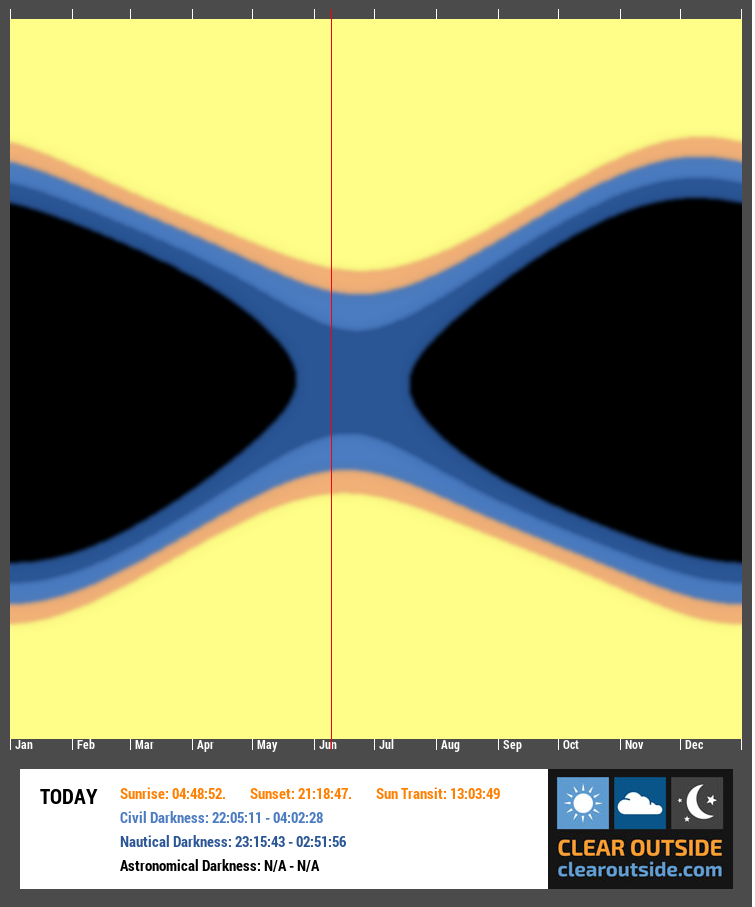
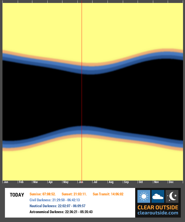
Given we are fast approaching the summer solstice, the nights are getting shorter and lighter. The Annual Darkness chart for IMT3 shows that we currently have no astronomical darkness and the nautical darkness lasts only for some 3.5hrs (left image) and now compare that the darkness graph for Mount Teide in Tenerife (right image) and although we lose some dark hours around the Summer Solstice it’s not as much as is lost being located at 52°N.
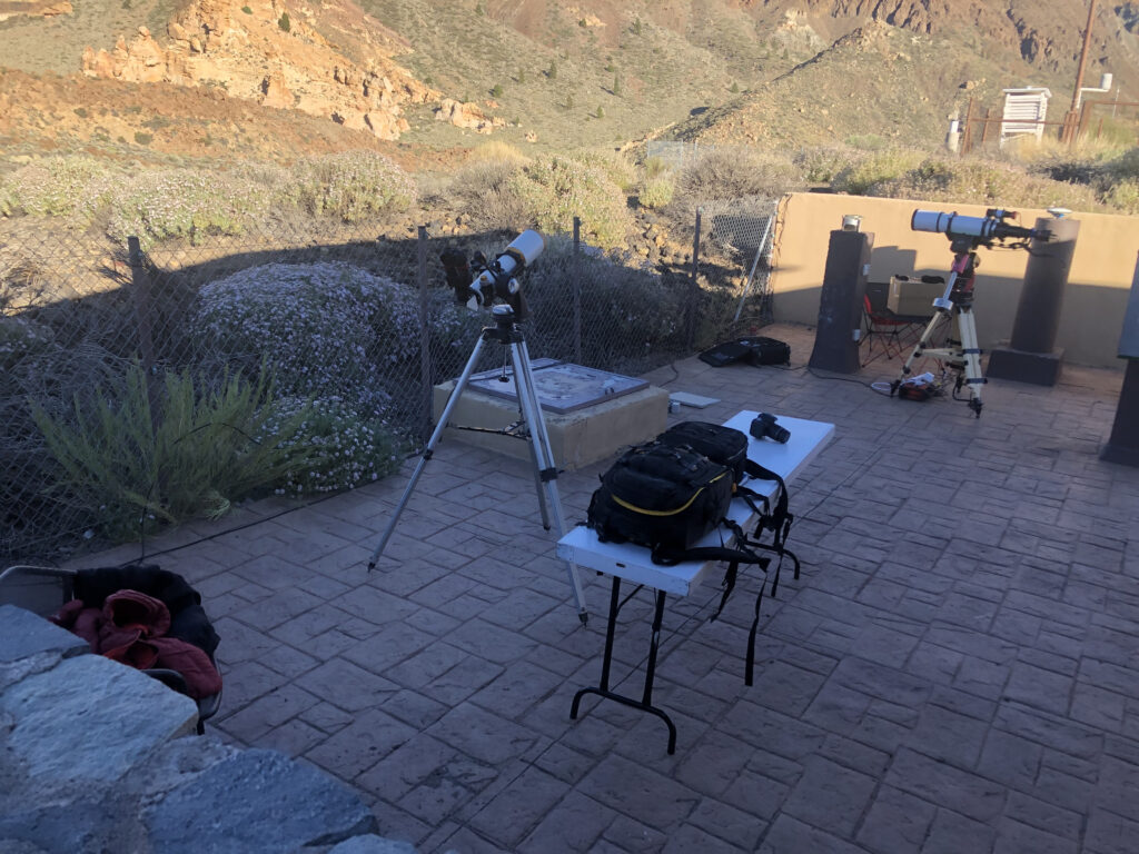
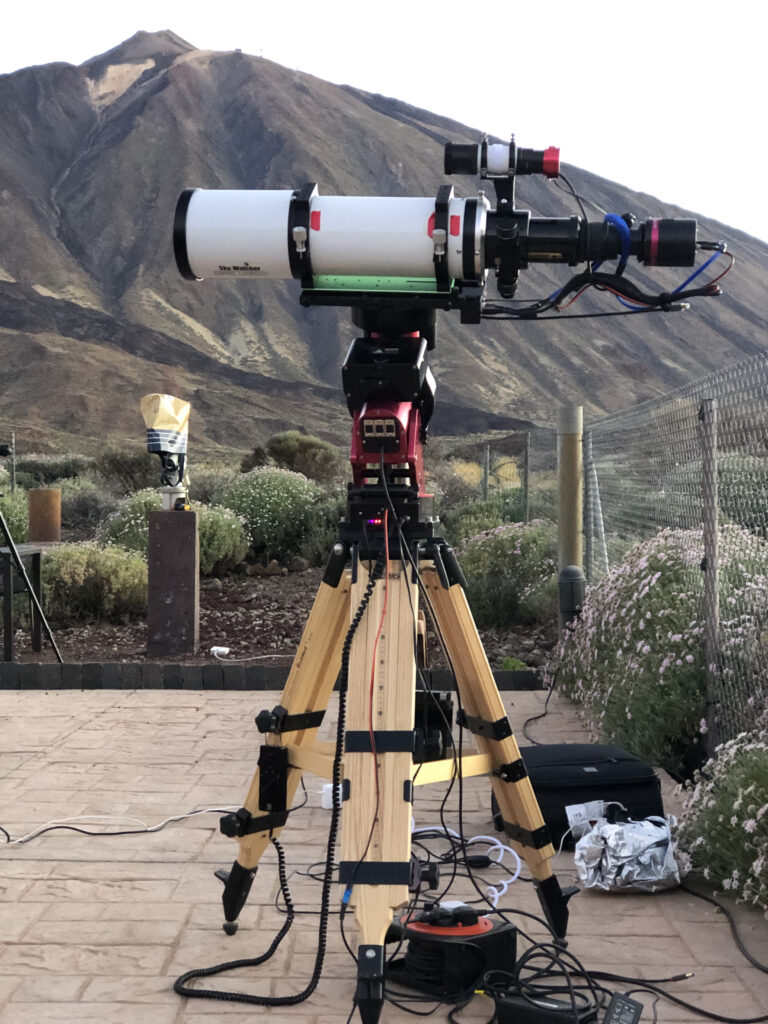
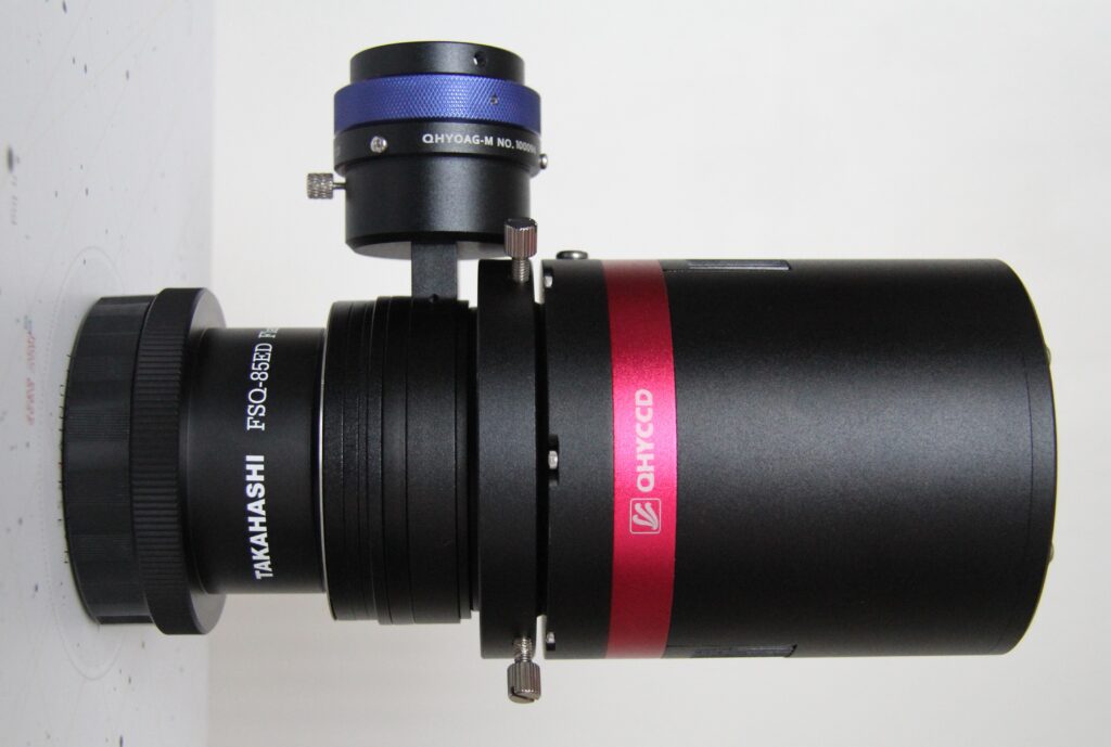
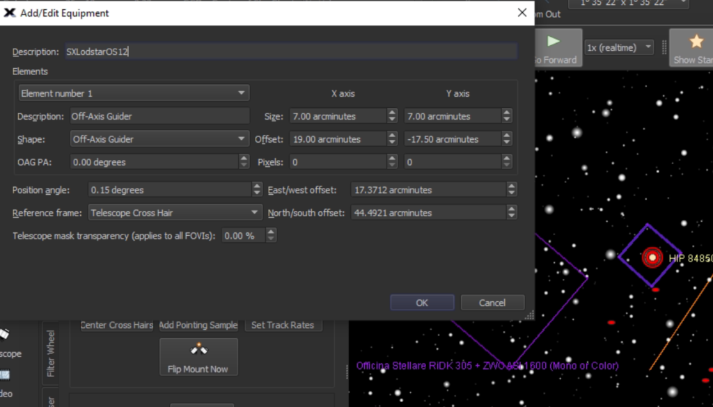
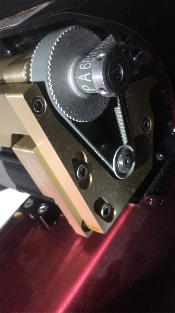
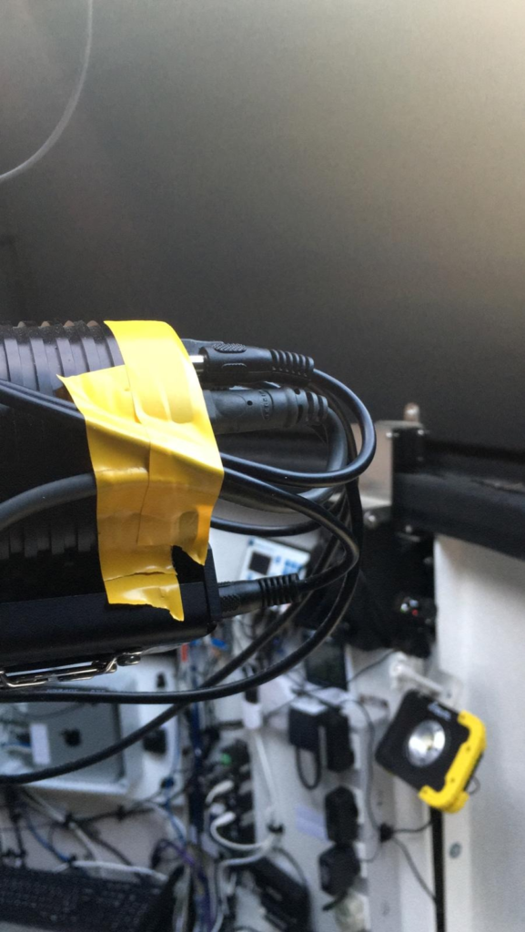
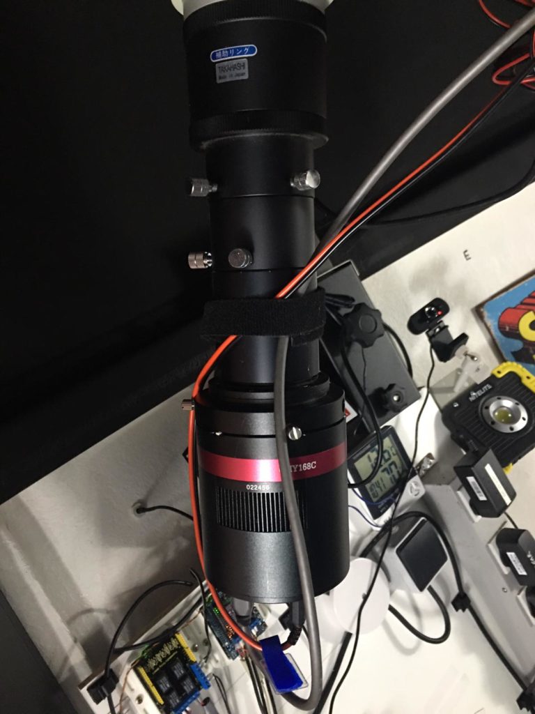
Setup – added BlueAstro stick station to measure pressure as Pegasus have not exposed the pressure measurement from the NYX101 mount to the ASCOM layer … why not ? Added weight bag to NYX-101 and GL.inet travel router to top of the scope as MS Windows keeps messing up the Wi-Fi hotspot on the Mele Quieter3C if it does not detect a internet connection ….. how stupid is that. Now I have a permanent hotspot thanks to the instructions given by Cuiv the Lazy Geek on his YouTube channel.
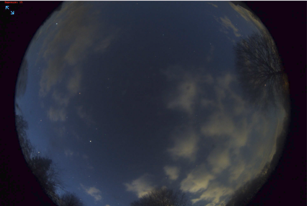
When attempting to polar align when using the QHY PoleMaster I noticed that the sky brightness below 15 mag2/sec (measured by a Unihedron SQM) produced a white screen due to over exposure – the minimal exposure in the now aged the QHY PoleMaster software (> 4yrs since last release) was 50ms which is too long even though I could eyeball Polaris in the early evening sky.
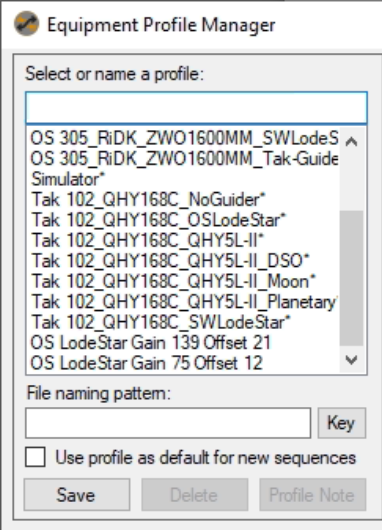
NINA 3.0 start up had not detected the QHY native driver and after I shutdown and restarted the app it then was able to detect the QHY 268C camera. However, it disconnected when it could not cool to -10℃ which I’ve never encountered before. I did eventually managed to get it cool and stay connected.
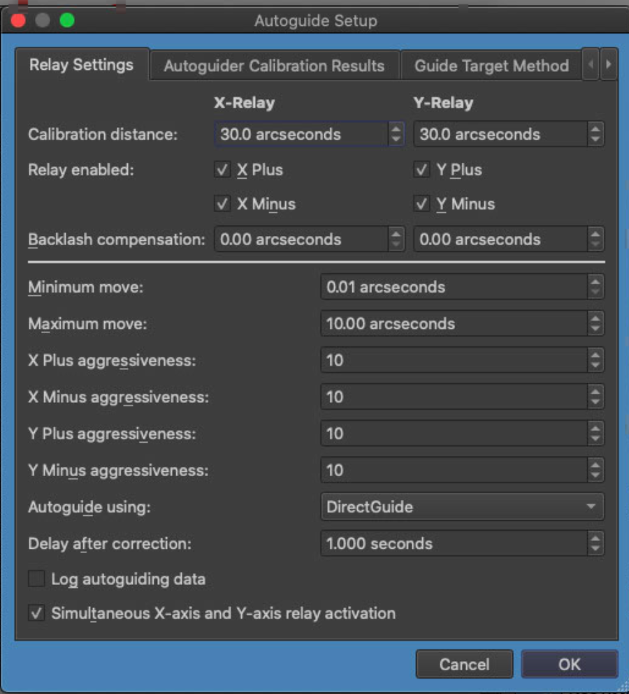
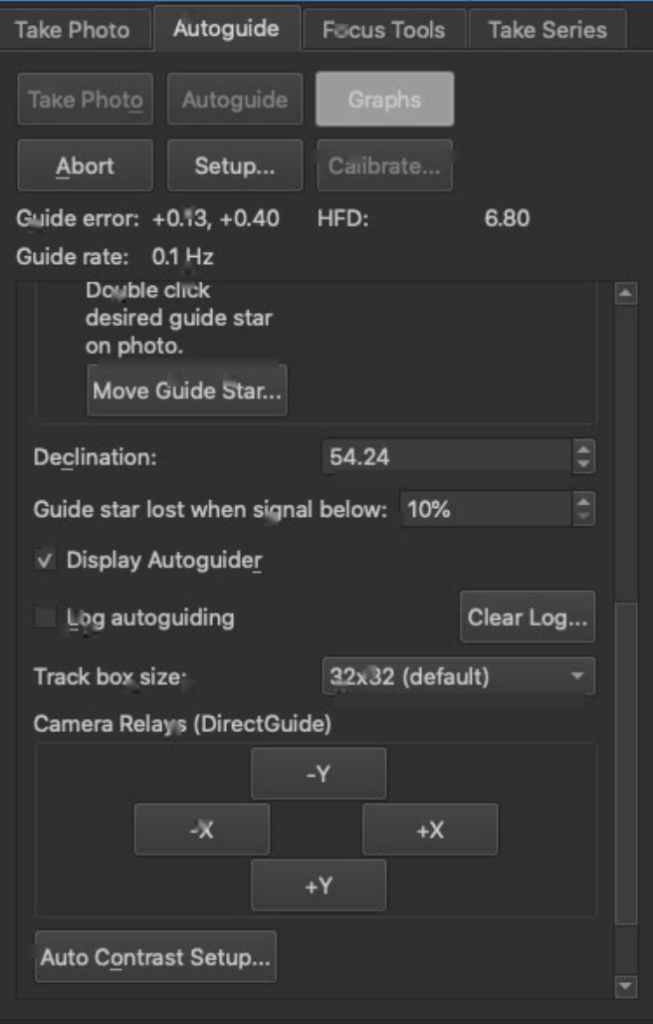
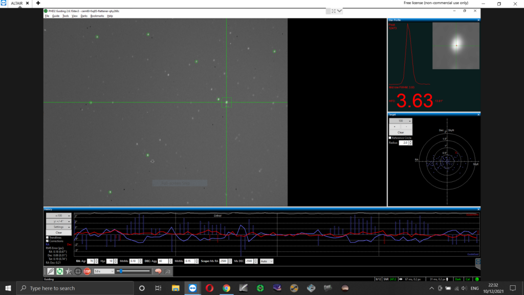
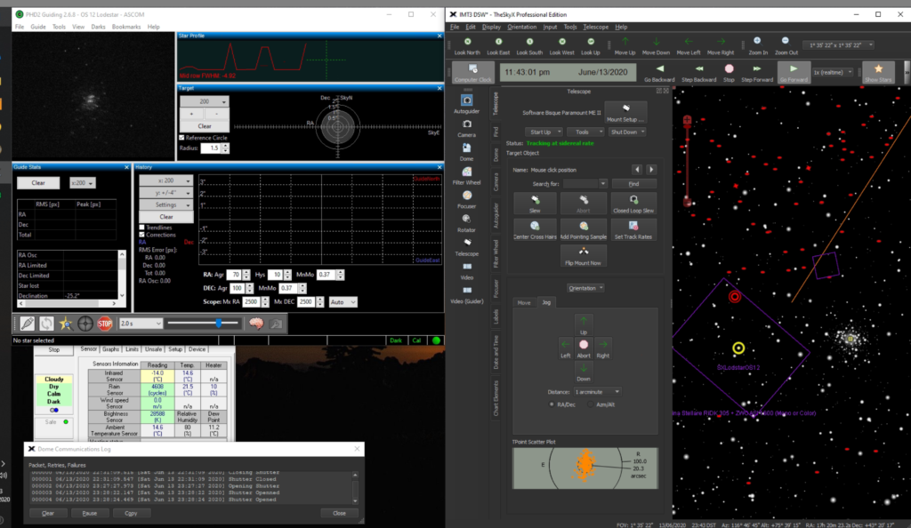
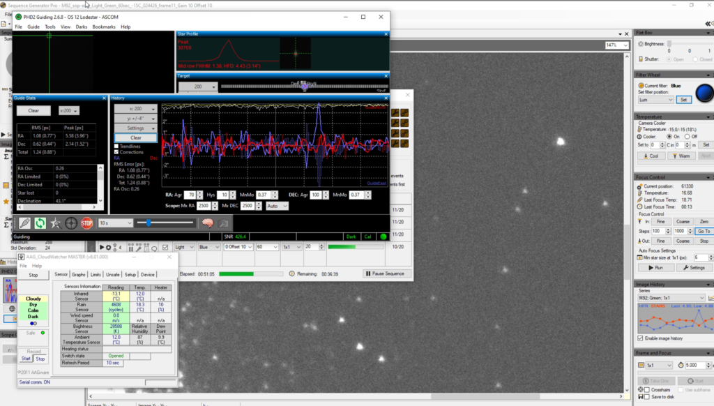
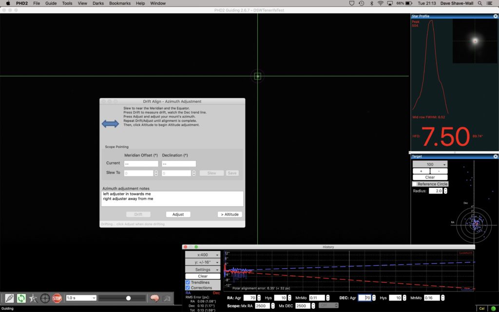
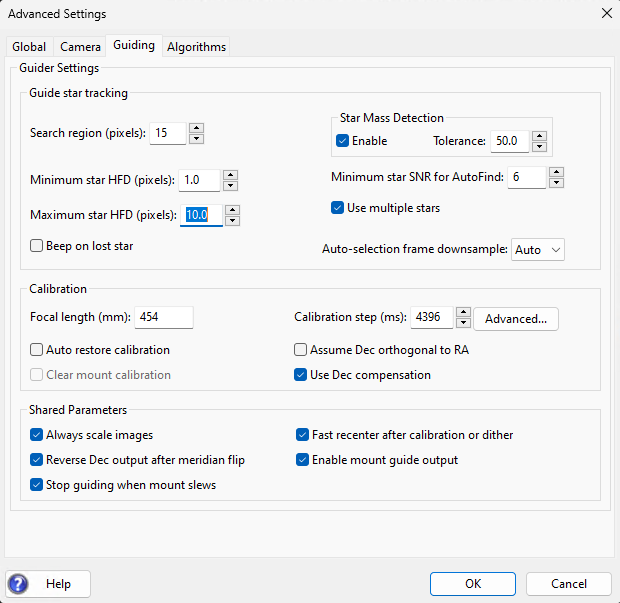
During guiding calibration OpenPHD2 would constantly complain about losing the star. Again the star was clearly visible on the PHD display and after downgrading from 2.6.13dev4 to dev3 and then I suddenly realised the value the error was referring to. I changed the minimal star HFD down to 1.0 from 1.5, also recreated the dark library to remove the possibility of the guider attempting to guide on a hot pixel.
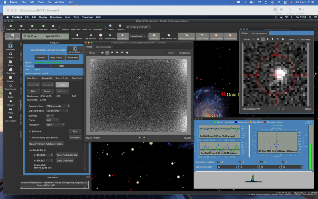
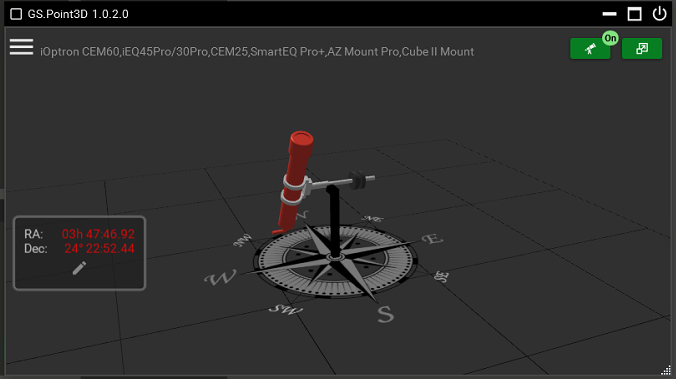
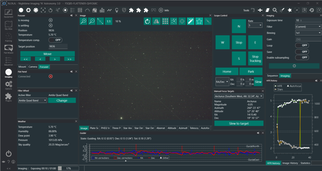
Once guiding, the guide graphs were reporting 0.08 – 0.19 arcsec total polar alignment error. Hopefully I will learn to improve that and maybe repeat the polar alignment procedure or use PHD drift align to refine it.
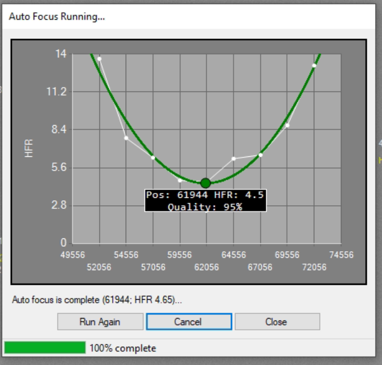
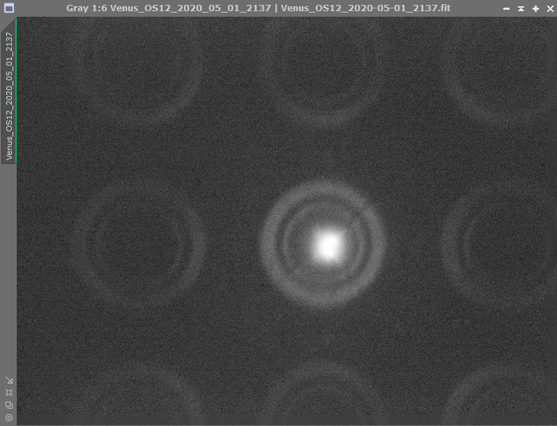
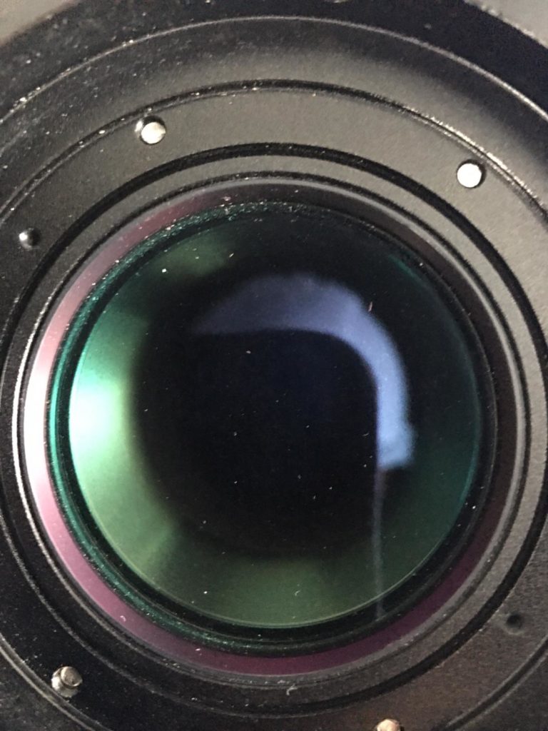
I also forgot to change filter at the start of the evening from the Antila Quad Band filter to the Baader UV/IR filter. I noticed a halo from the bright star Arcturus in the constellation Bootes which I was testing autofocus on but I decided to continue regardless as I was only testing.
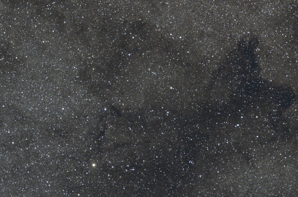
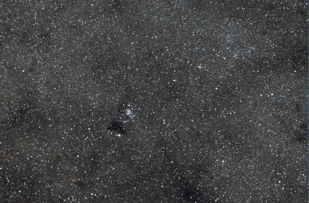
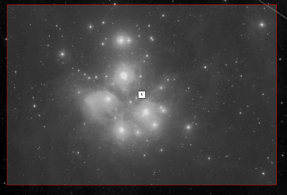
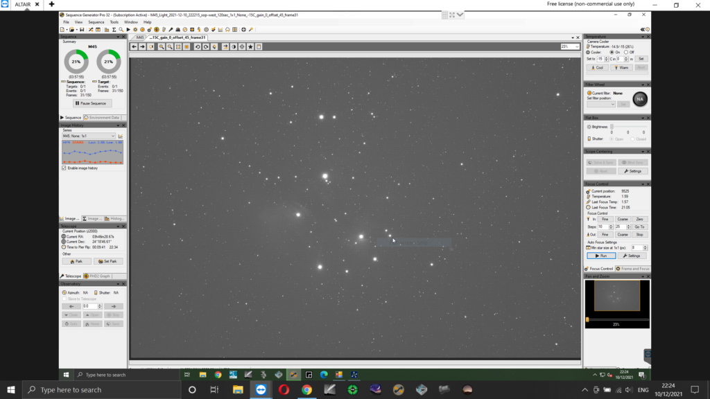
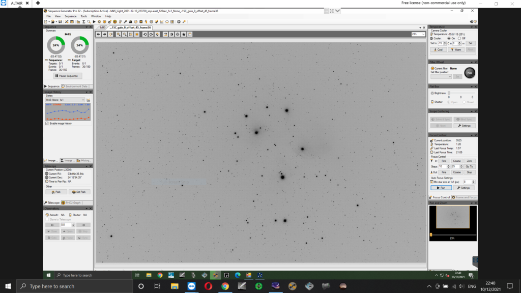
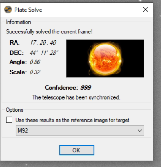
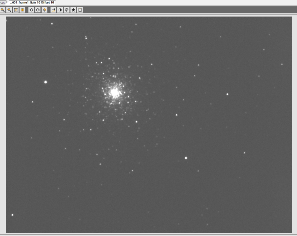
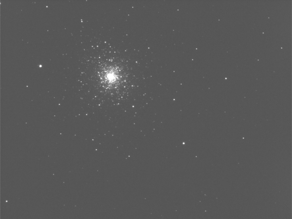
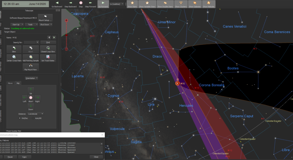
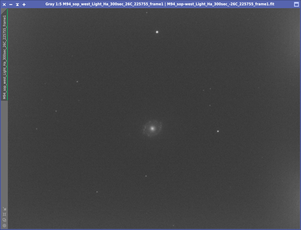
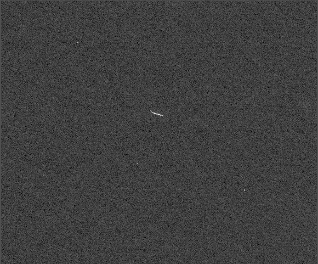
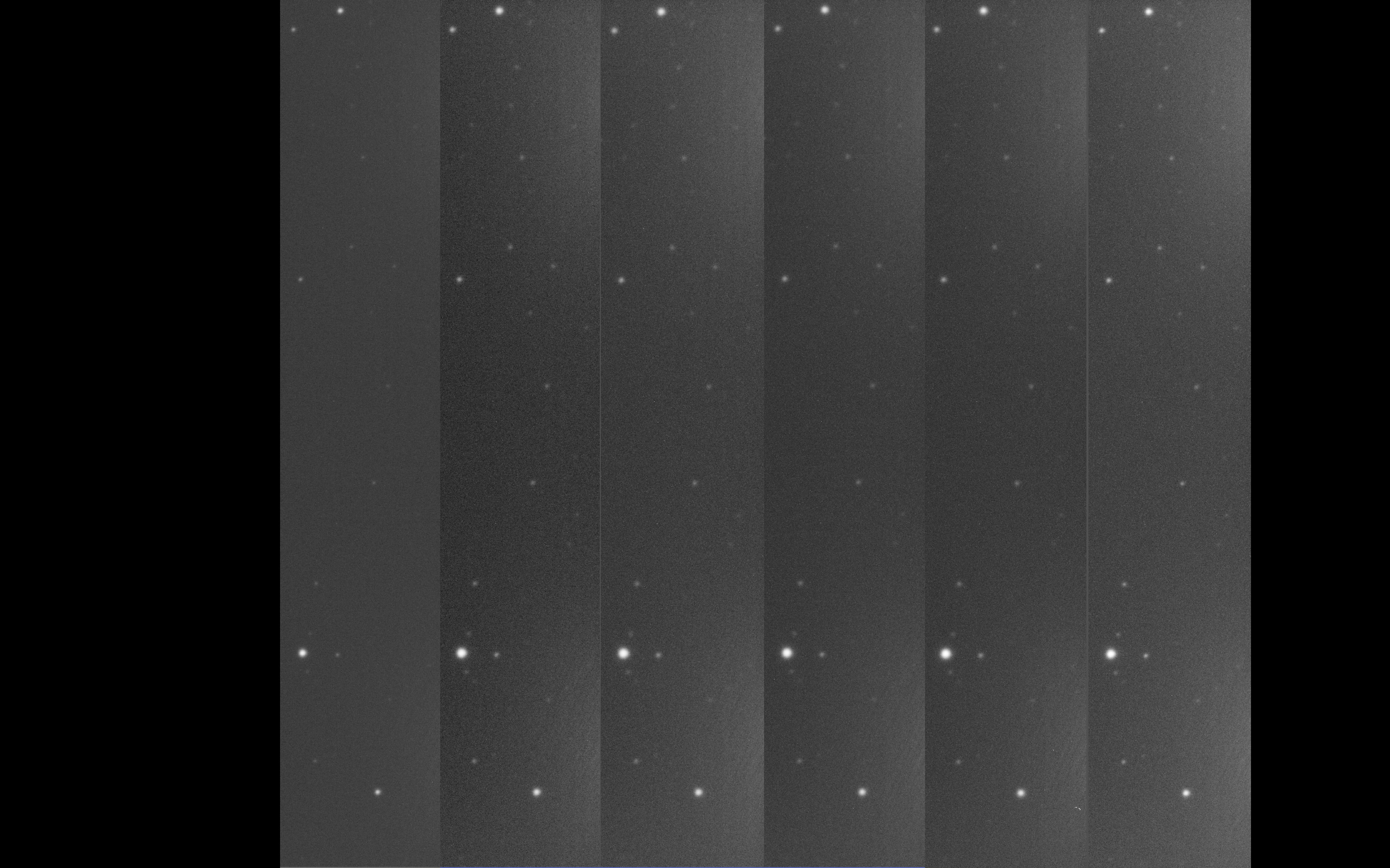
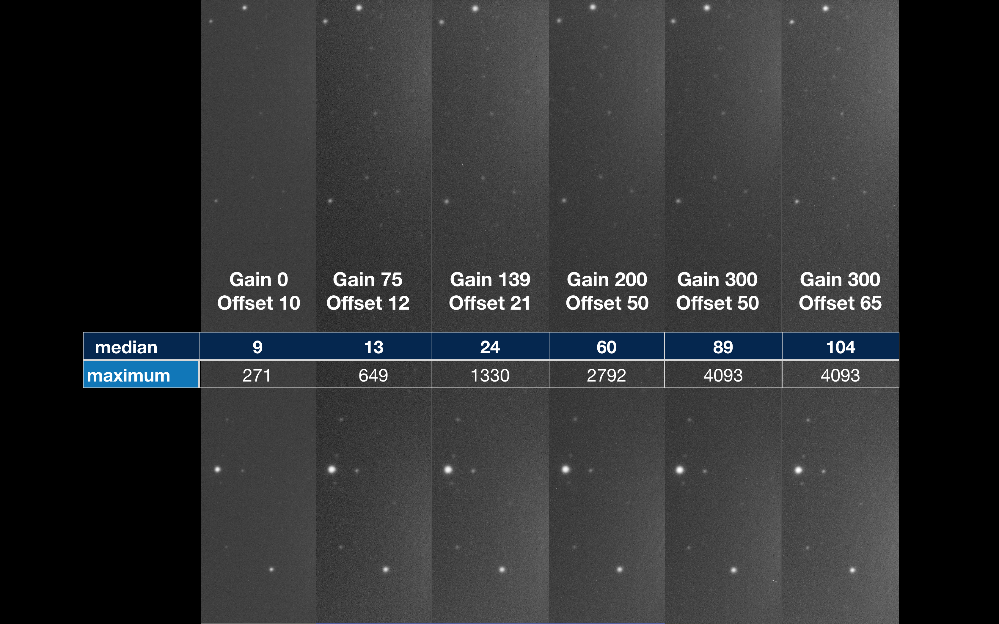
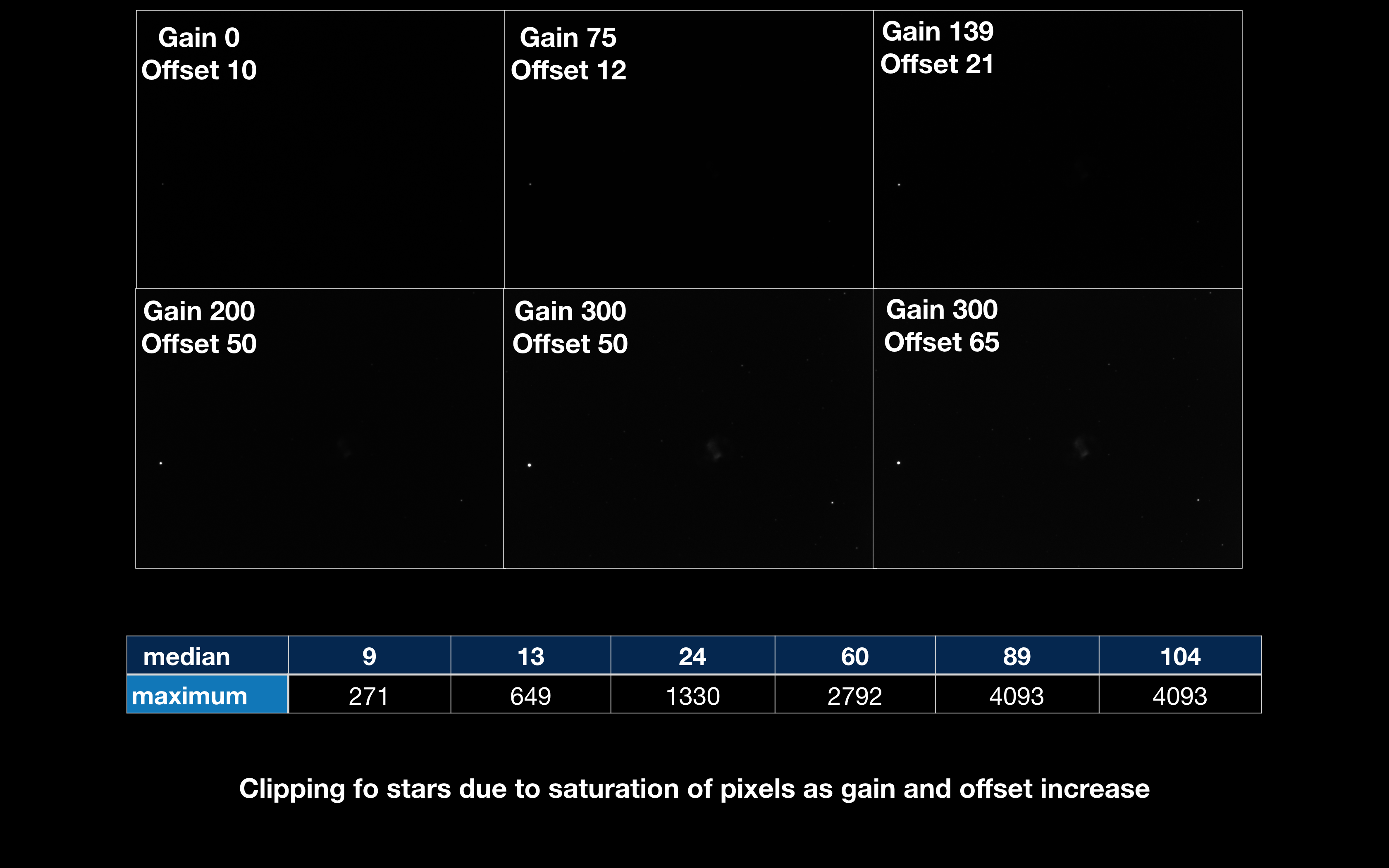
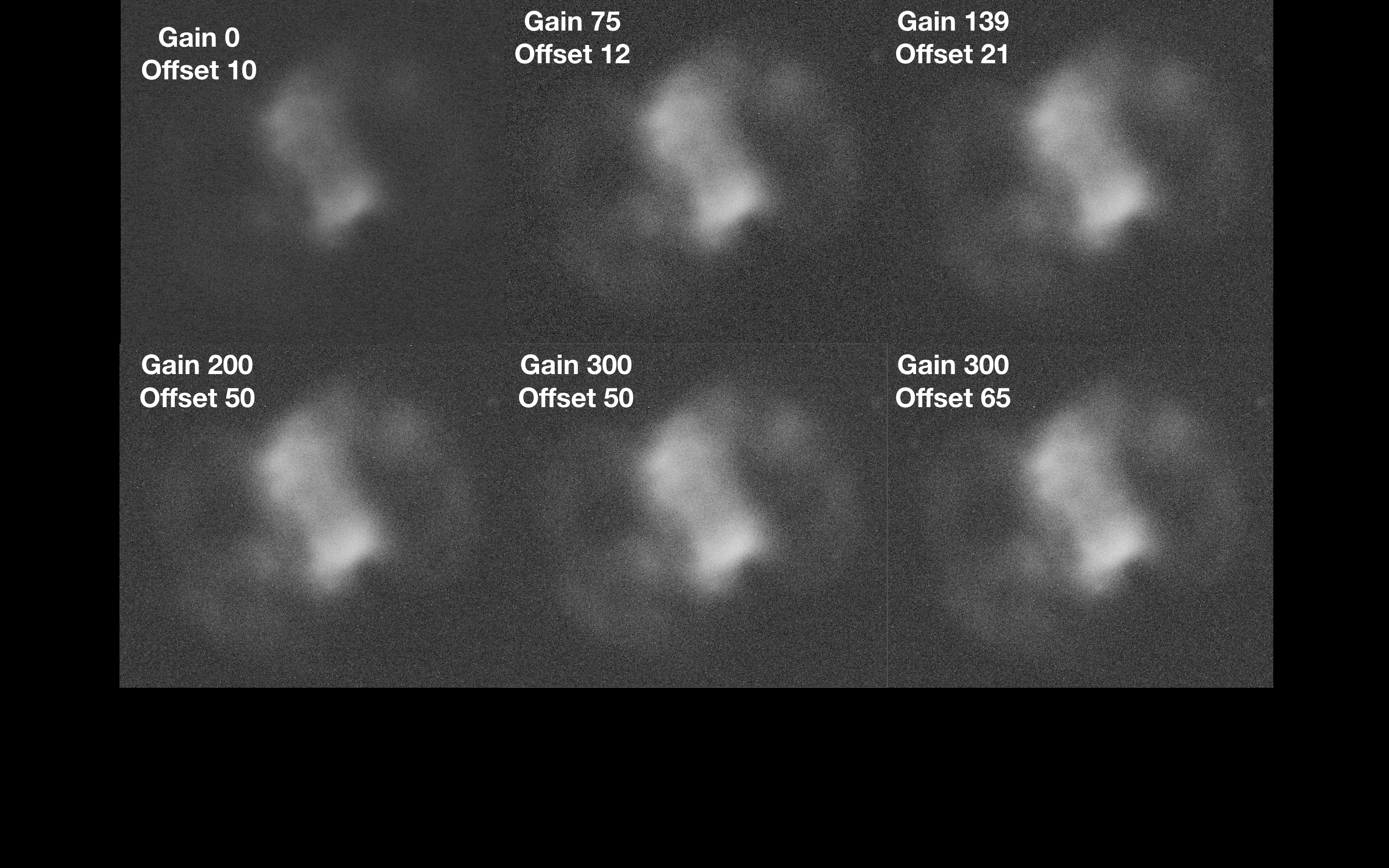
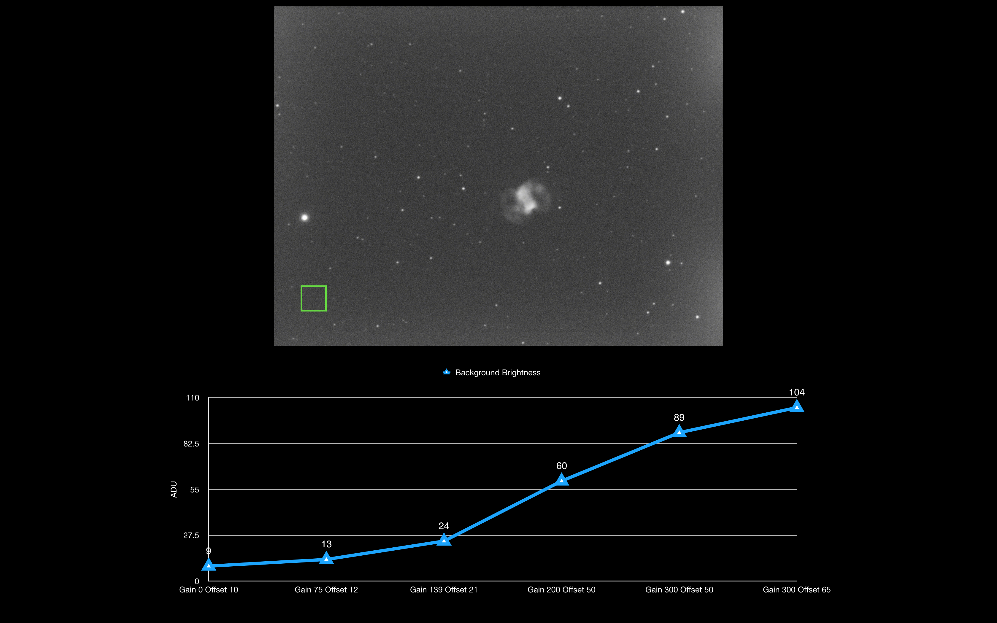
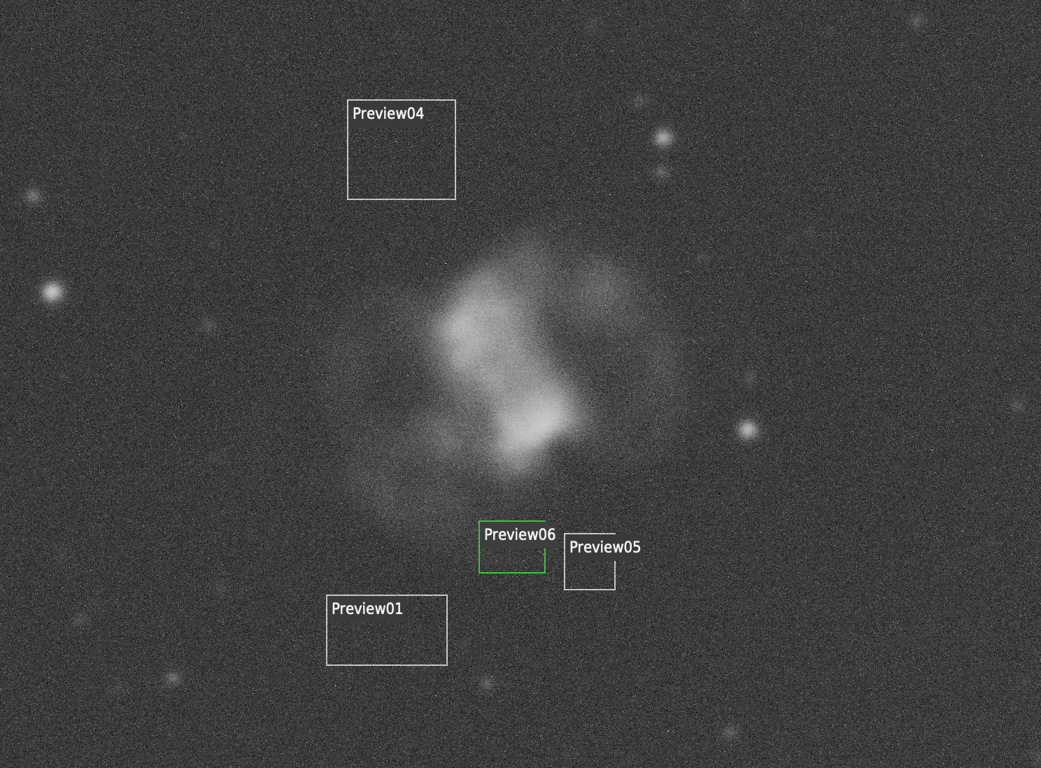
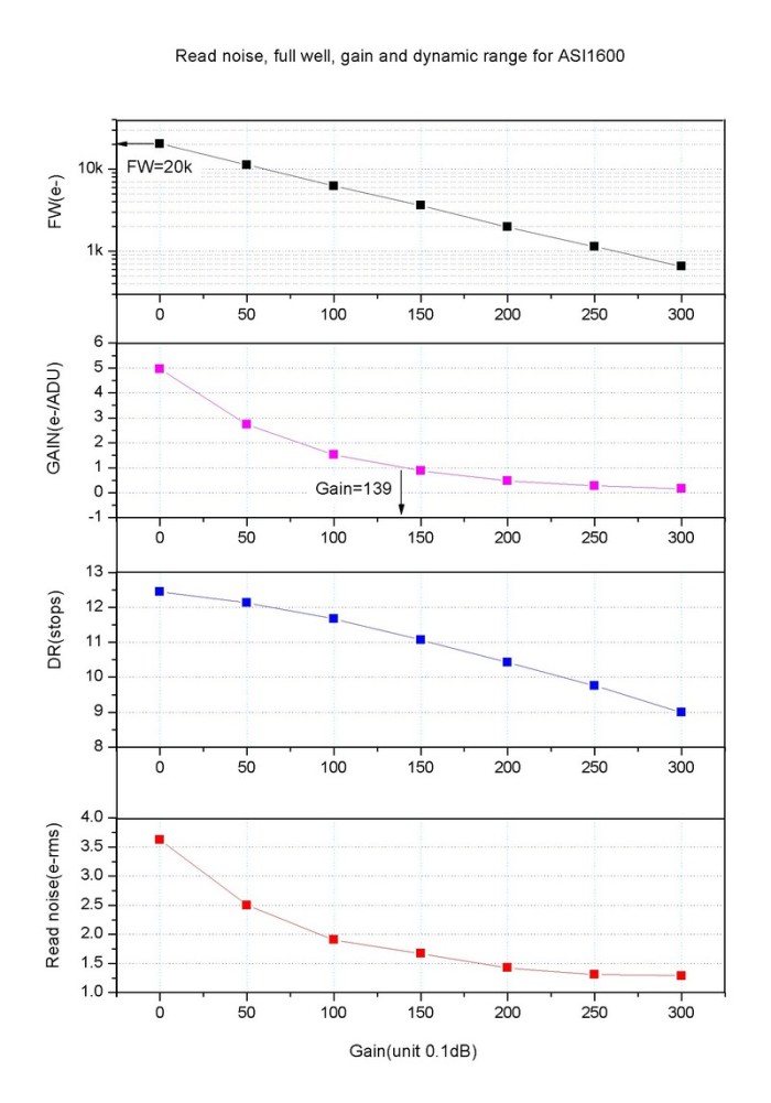
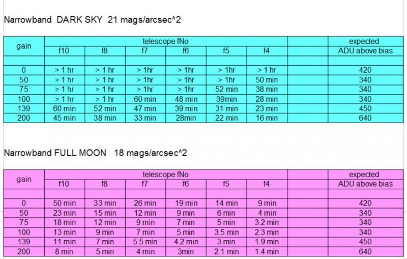
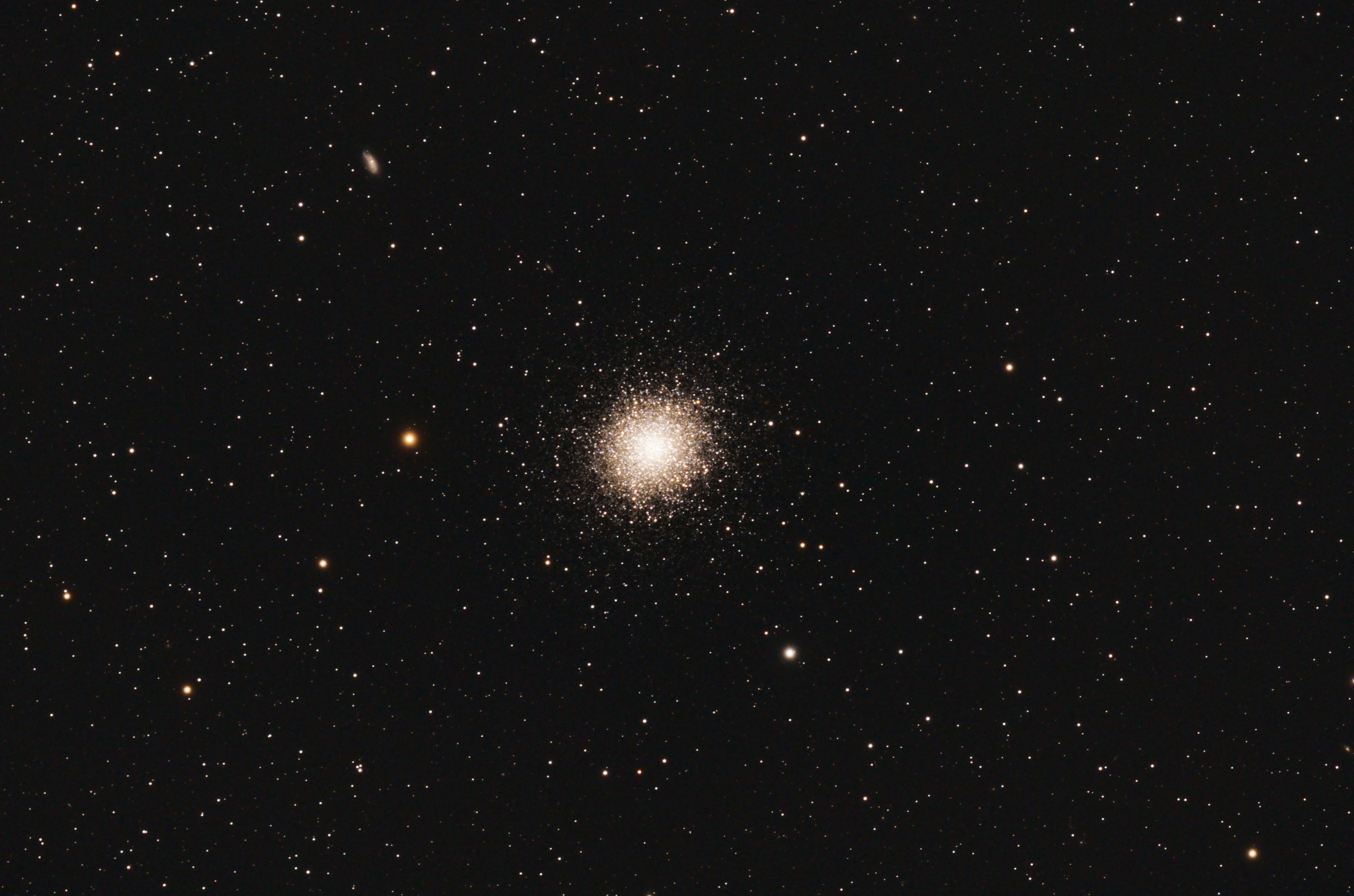
The goal for the night was to grab a base image of T Coronae Borealis (“The Blaze Star”) before it goes nova – it’s a reoccurring nova with a 80 year cycle. The star is currently hovering around 10.2 magnitude and it is predicted based on previous eruptions to reach around magnitude 2. As I ultimately wanted to perform some photometry on the star using the UV/IR cut filter I did want to blow out the cores of any bright star so I opted to use the ExtendedFullWell2CMS mode at gain 0, offset 30 with 60 second exposures. During the sequence I forgot to watch HFR/Star count graph and it rose above 5 which meant I have to refocus to (HFR ~2.0) and so due to my oversight due to chatting I will have to dump a lot of the early subs.
At the end of nautical darkness I stopped the sequence and used the NINA flat wizard (dynamic exposure) with the old PegasusAstro 120 flat panel at 100% brightness to create 25 flats and flat darks for a target of 33% ADU. After packing up and the with the pre-dawn temperature hitting 4℃ just before 4am I was looking forward to getting to bed.
At the next clear non-working evening I will attempt to grab some subs again but this time using the correct filter. Thank you to Dave and family for hosting me once more.
NB – NINA 3.1 was formally released the following day (09/06/2024) !