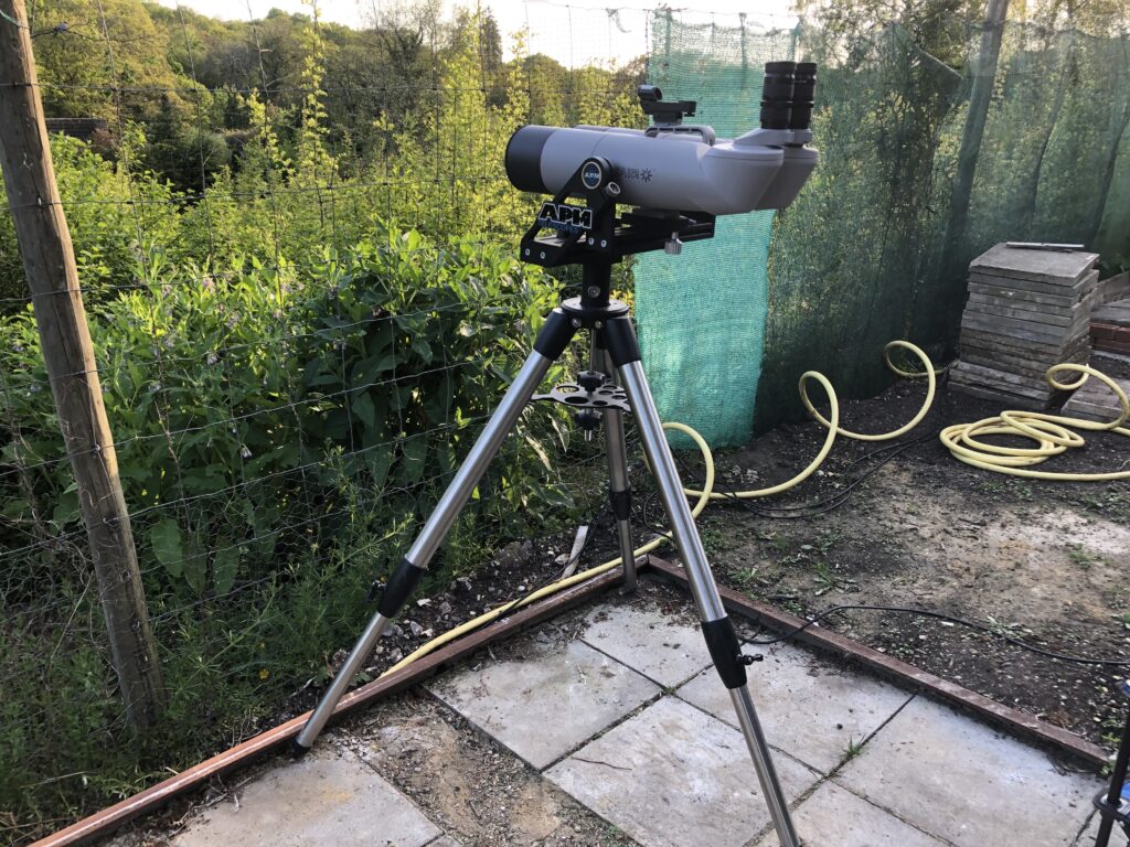
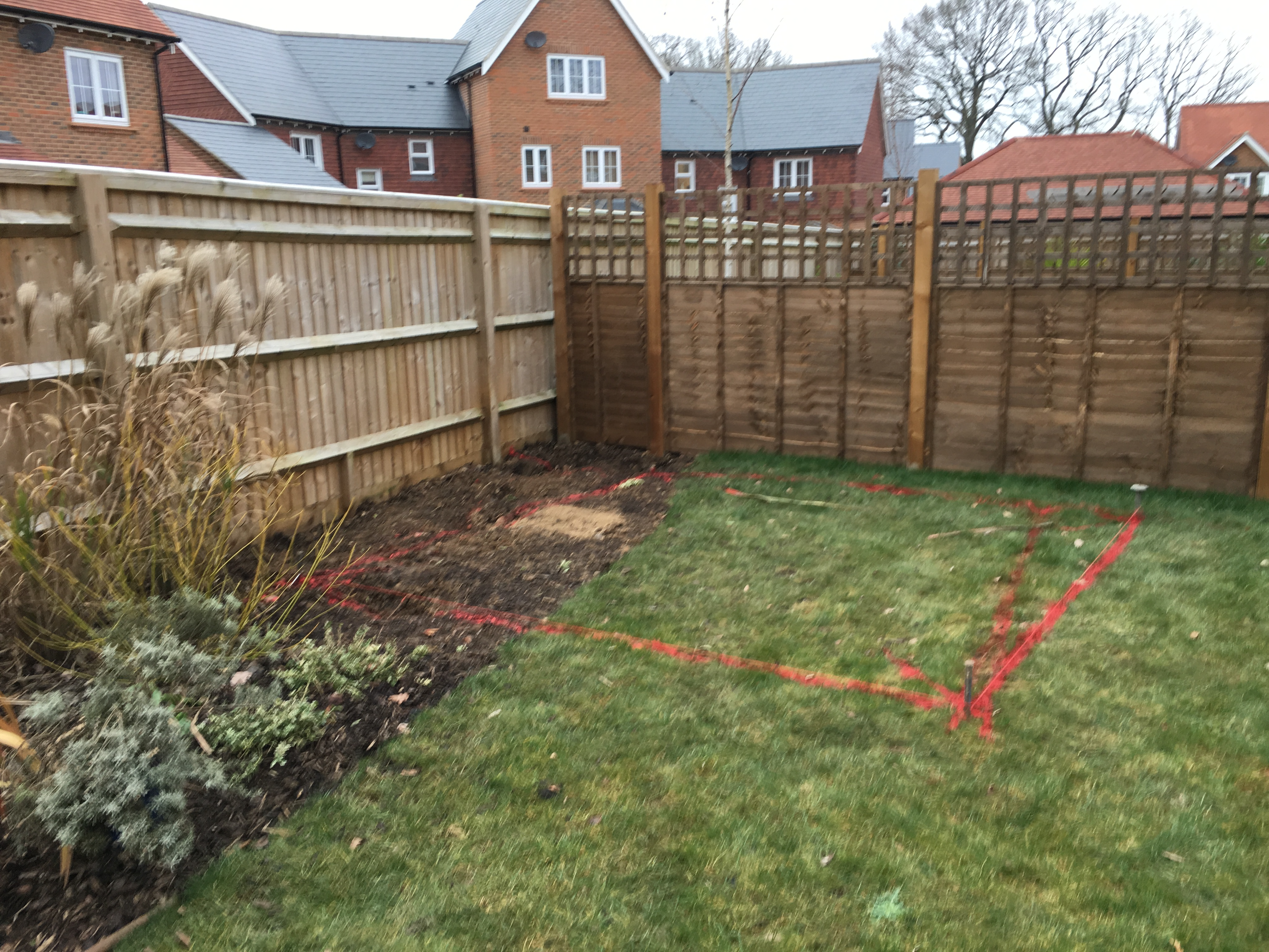
Viewing Report 1st June 2021 – IMT3b

20:37 – 03:15

Setting up

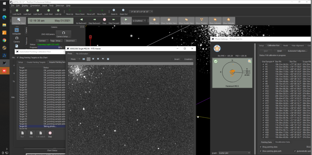
I will start by completing the TPoint run tonight before moving on to calibrate the guider and make sure I can get and image. So by 10:30pm it was just on the border of being dark enough to take and plate solve the first image and continue the TPoint session.

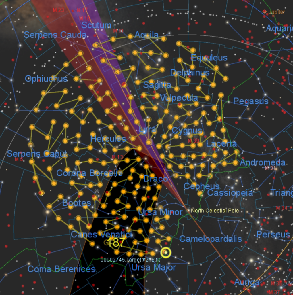
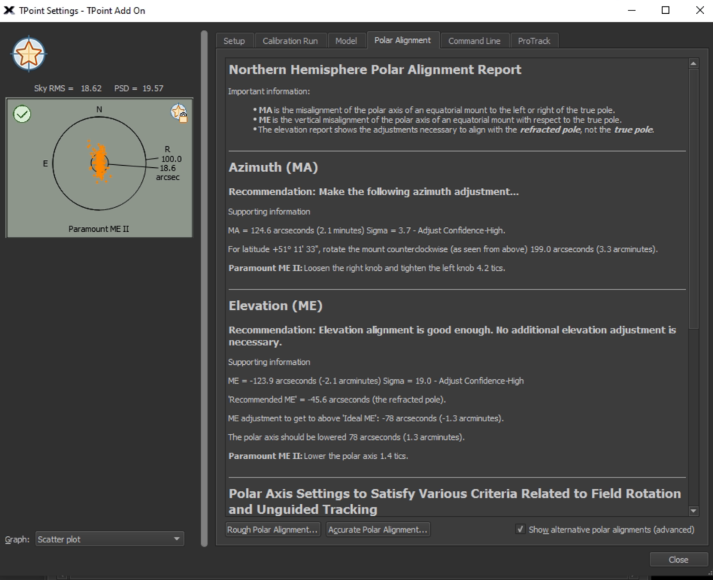
So by 11:30pm I had finished the 212 TPoint model.

212 TPoints

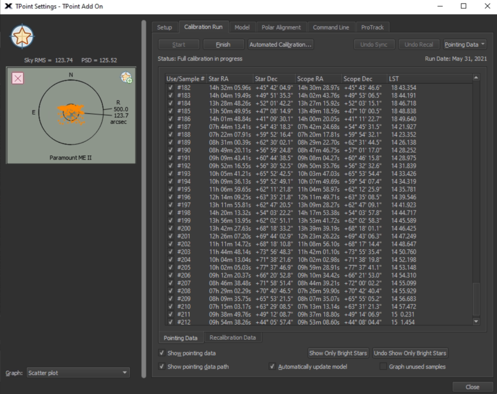
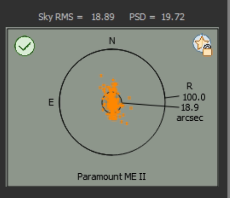
The next thing was to do a Supermodel on the data. This reduced the error pointing from 500 & 23.7 arcsecs to 100 & 19.

Model

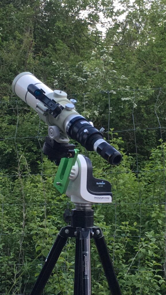
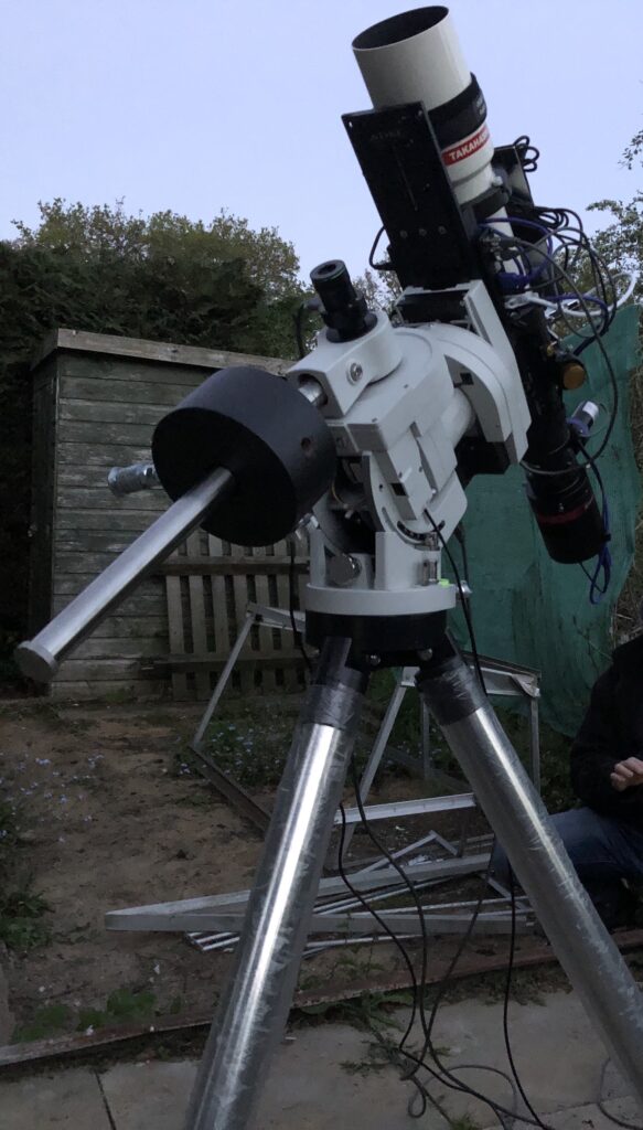
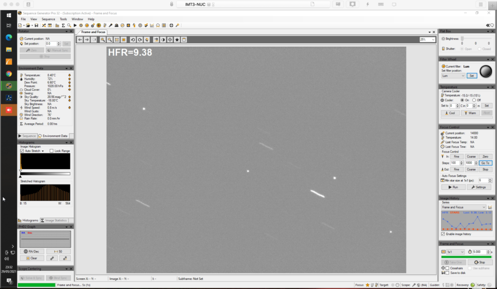
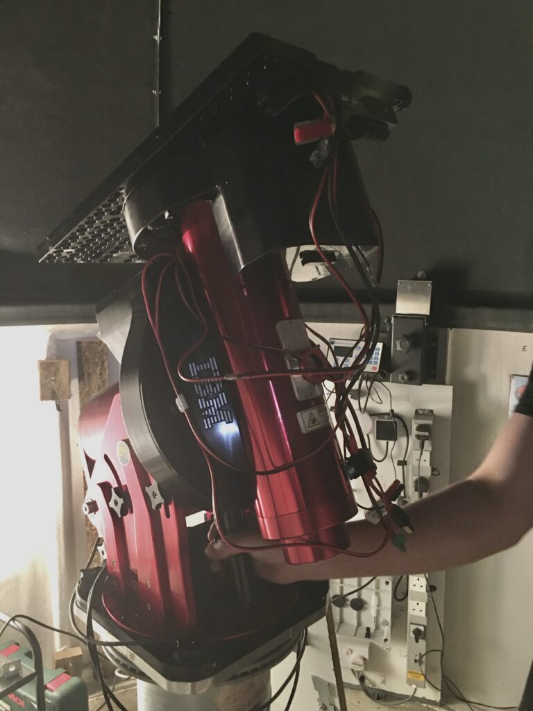
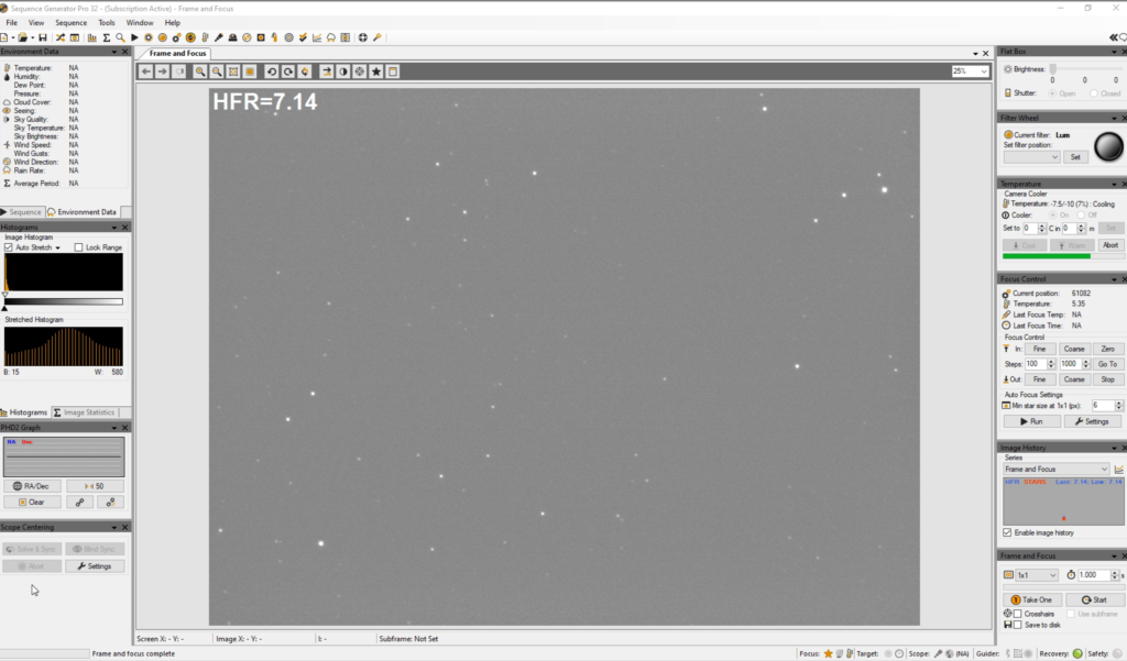
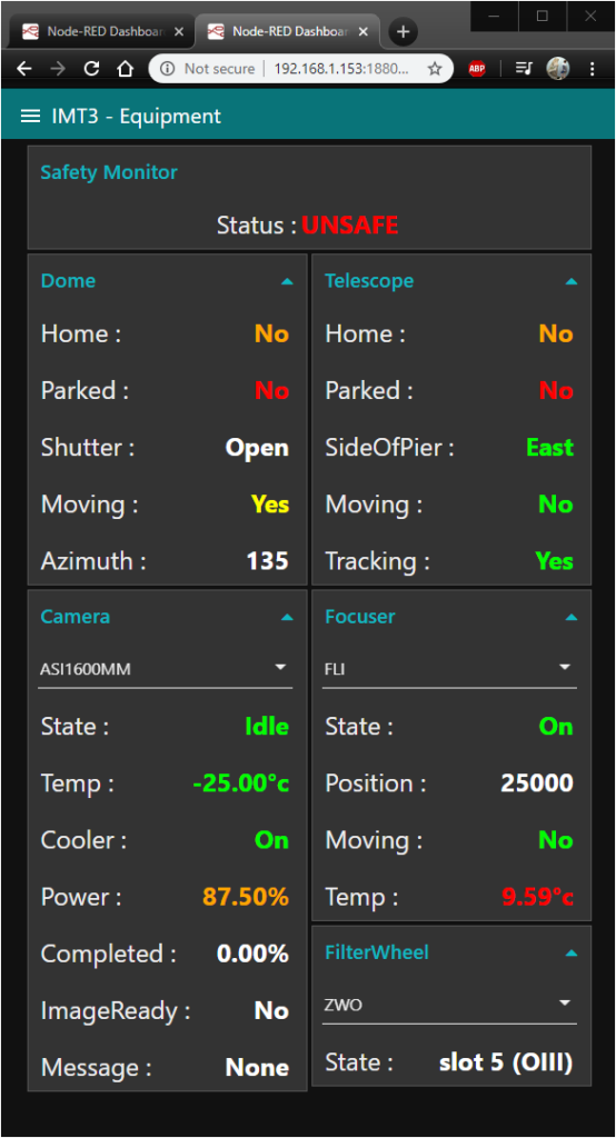
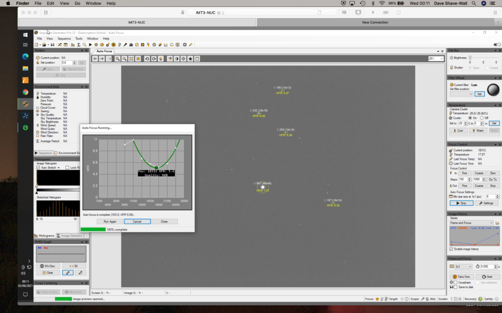
Now connected camera to SGP and running autofocus on a mag 6 star, new focus position for Luminance is 18,312 at 00:13

New focus position

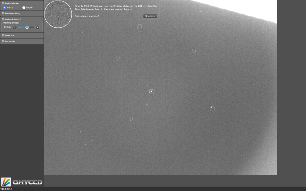
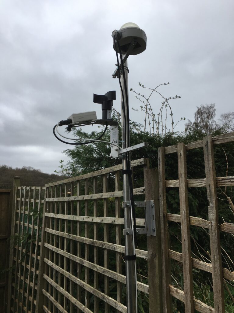
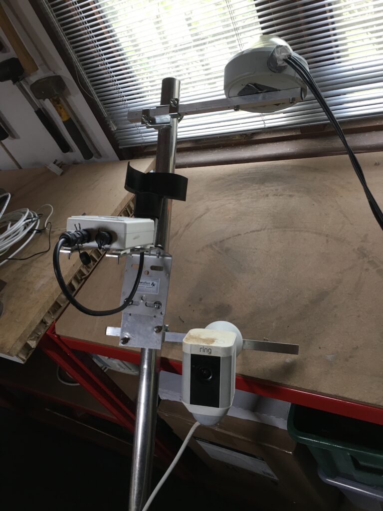
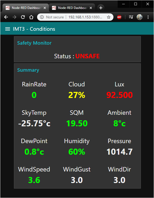
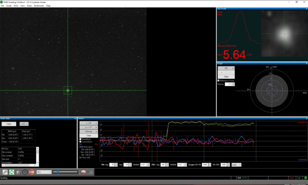
I then setup OpenPHD2 to guide and here I hit a problem. The guider did not move the mount. I have not got a guider cable attached as I do not want to do Pulse Guiding. Instead I always do Direct Guiding. So I looked at the settings in PHD2 and the mount was not set. So I went and searched my blog and I need to select the ASCOM Telescope Driver for TheySky. However it is not in the dropdown list.

ASCOM Telescope Driver for TheSky

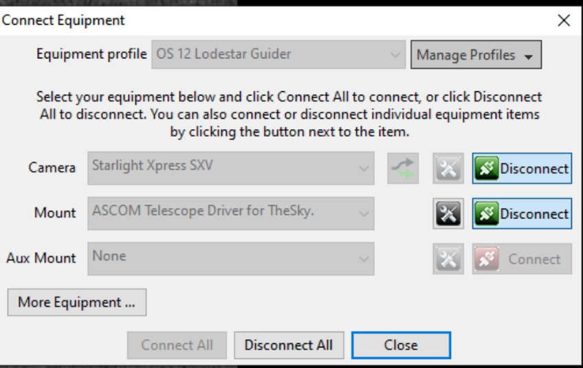
Finally after a lot of head scratching I remember GingerGeek removed ASCOM and upgraded when I moved house. He had inadvertently removed the said driver and forgot to reinstall. I went to the ASCOM webpage, found the driver which took me to the Bisque website and downloaded. I then installed, restarted TheSkyX using PHD2 after I had restarted PHD2, I selected the said driver in the Mount dropdown and connected. This then moves the mount when I calibrate and subsequently guide. Fortunately I found all these answers on my blog posts from last year when I had setup the guiding originally.

Finally guiding

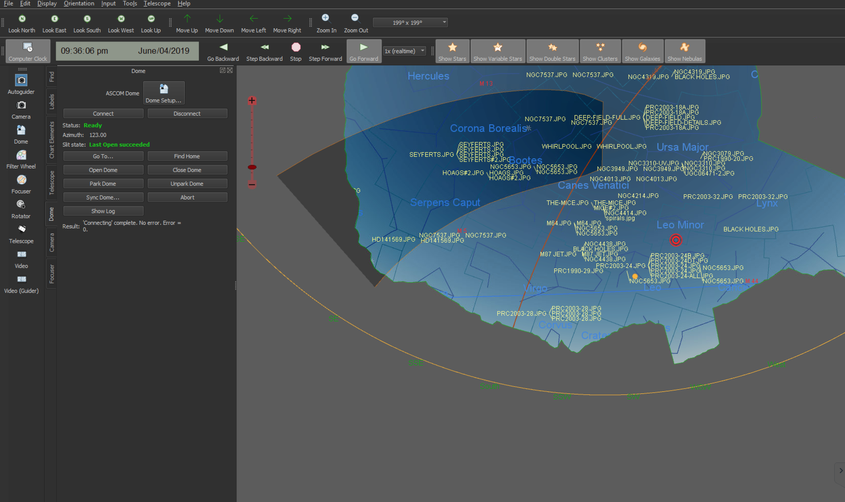
Now all of this is working it is rapidly approaching the time when the sky brightens, so it is already after 1am. I slewed to M14 using TSX, performed a Closed Loop Slew with the camera connected to TSX initially. Once I confirmed the object was in the centre of the FoV, I then disconnected the camera from TSX and reconnected to SGP.

M14

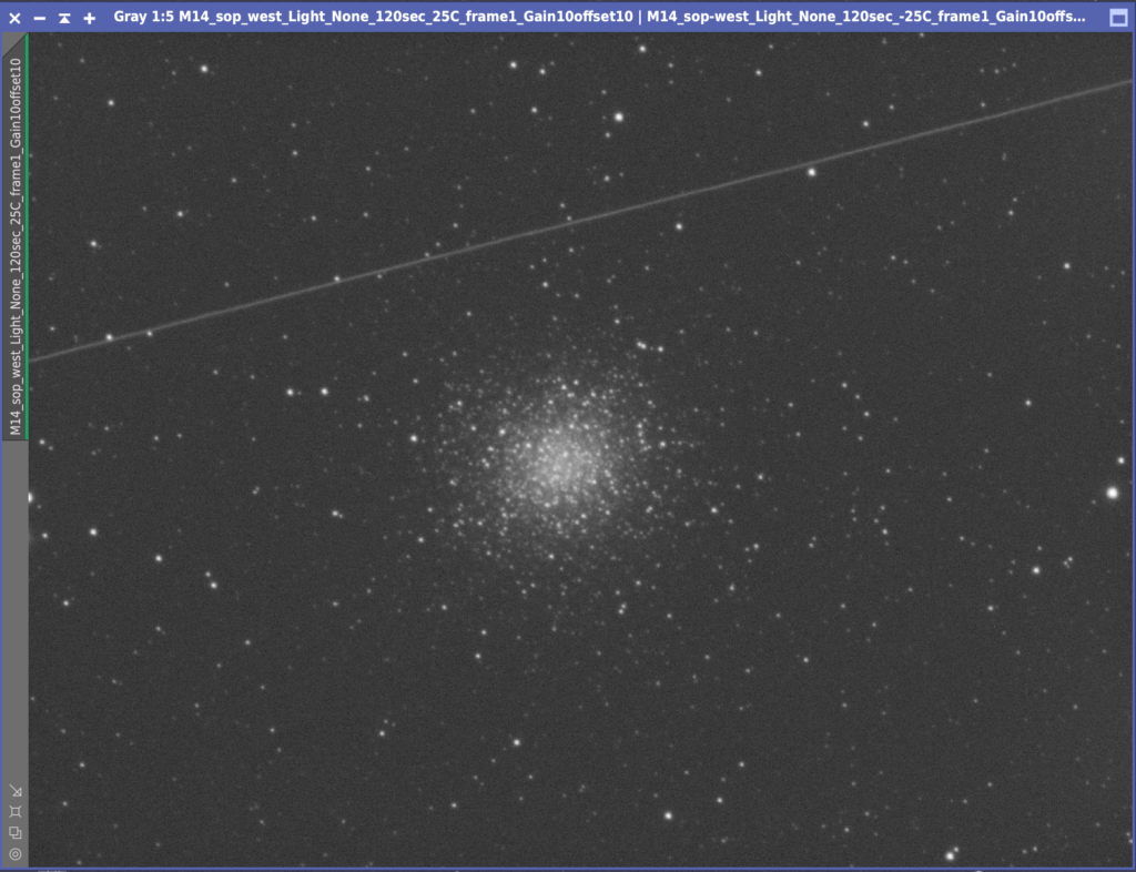
Guiding started, all started to work well. A couple of snags, focus position was wrong in the filter setup so I need to change. Tries to autofocus on start of sequence so I need to change that. I then decided to grab 1, 2 and 5 min subs of LRGB to determine the best exposure. However half way through and some localised cloud rolled in and stopped the session.

Clouds

The good thing its the closed loop slew is working well in TSX.

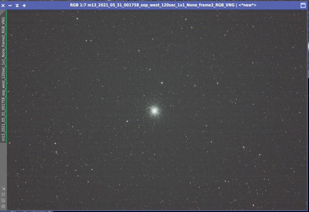
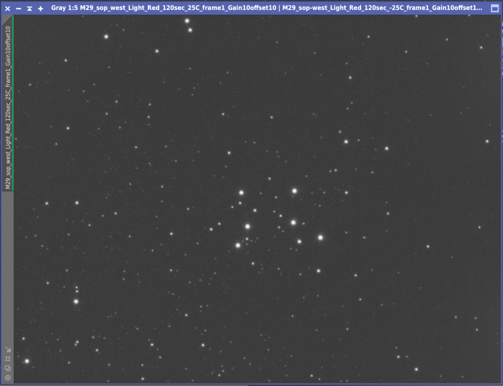
So with the local cloud still causing issues to the South, I slewed North East to another Messier target on my list, M29. Once again I setup 1,2 and 5 min exposures across LRGB to see which would be best. All the imaging tonight for Globular Clusters and Open Clusters was done at Gain 10 Offset 10.

M29 test 2mins Red

I manage to get frames and then I was afflicted by the same cloud. So instead I packed up and called it a night.

Viewing Report 31st May 2021 – IMT3b

19:25 – 03:28

Bob came over again tonight which is great company. He setup his Skywatcher AZ-GTI portable mount with his Tak FS60 on it so we could do visual throughout the night on a goto mount along with my star hoping through the 100mm binos.

Skywatcher AZ-GTI

I started the evening whilst light, measuring for the replacement T2 (M42) adapter for the camera train. Given the 0.083 microns per movement of the FLI Atlas focuser I need to reduce the image train length by 3mm. So the new adapter needs to be 31mm, current M42 adapter is 35mm. Meanwhile my AstroCat Fluffy decided to get some more sleep before dark.

Fluffy taking a hard earned nap

Next up was writing the Lat Long on the dome so I can give it to anyone that visits. With that done I started testing the rotation of the dome to make sure the dome no longer slips since I put the anti-slip tape around the edge. After spending some 15mins rotating the dome it seemed ok, it would be fully tested later when I redo the Tpoint model. This is due to the 2.1 arc minutes of error in my azimuth polar alignment that needs adjusting by 4.2 tics.

I adjusted the mount as above and ran a 20 point model. This told me the error int he azimuth was less than 1 arc min and that there was no need to adjust the mount any further, however it had low confidence. So now I will run a full 212 Tpoint model to see what it reports.

212 TPoint Model map

On starting the run I hit another problem, the mount hung and beeped. This was due to a balance problem on the tube which is weird as I thought it was fine. However maybe I had not rebalanced since adding the rotator properly. I removed a little weight at the front of the OTA and shifted it backward. I then tried again but again it hung and beeped. It transpired to be the same loose cale I had before, the focuser cable which had come loose. I applied some more white electrical tape to hold it in until I get round to changing the 2.1mm adapter.

At 23:40 I started a new TPoint run and am now 7 stars in and all is well. That did not last for long, around 47 Tpoints and I kept getting blank images. It seems the dome had lost its position. The Home sensor does not seem to be registering. I slewed the dome manually to Home at 123 degrees and synced that back into the dome controller. Starting the TPoint again resumed stars being seen.

Meanwhile Bob was moving from object to object without the AZ-GTI mount. M5, M57, M10, M12 along the way. We easily split Albeiro although Bob was slightly worried about my eyesight as I initially struggled. We saw the head of Scorpius pop up above the tree line but we didn’t get M4 from the IMT Plateau and Antares only just made it above the tree line. So I decided to relocate my bins to another spot in the garden by the Sun Plateau so we got M4 through them. M17 was seen through he 100mm binos also, looking remarkably like a Swan! Finally as it got light just after 3am we nabbed Saturn, Jupiter and the Moon.

We could see the star HD 200329 and Titan along with Saturn

By the end of the night I was at 187 TPoints so not enough for me to be confident the whole sky was mapped, nor enough to fix the model and have Protrack running. I will continue the mapping when dark tomorrow night.

Viewing Report 30th May 2021 – IMT3b

19:30 – 03:19

GingerGeek came for a visit with his kit for a night observing.

Ioptron CEM60, FSQ85, QHY OAG, SX Lodestar, QHY268C CMOS, Pegasus UPBv1

So whilst he sets up I have been testing the rotation of the dome as it still jams. After some testing I now believe the only fix is to find some grip tape that will add as friction to the inside of the dome between the dome itself and the thruster wheel. I have found some anti-slip tape on Screwfix which is 50mm wide and 18M long for £10, which will do the trick.

New Anti-Slip tape

Just watched the ISS go over, first time for GingerGeek. Videoed it using the iPhone 8 and it came out great. Also have the lovely noise of an owl in the background.

ISS passes overhead

Started Tpoint at 11pm. Used 30 second exposures and image scale of 0.33 arc/pix. I am performing a 212 point Tpoint model.

Tpointing near a globular cluster

Well TPoint model complete, of course I forgot to initially do around 25 TPoints, adjust the polar alignment which is our in Azimuth by 2.1 arcmins and then rerun.

TPoint results

Meanwhile before we finished I ran one of GingerGeeks M13 images through PI as a single frame from his new camera.

M13 from GingerGeek (60 seconds, Mode0, Gain 0, Offset 30)

Started to pack up at 3:19am

Viewing Report 29th May 2021 – IMT3b

20:30 – 01:30

What a glorious day

Another long pause between observations, after what seems like 3-4 weeks if not 1-2 months of storms, gales force winds and rain. However, tonight Bob came over and now that I have the new rotator installed with the new adapters I could use the 12″.

Ready for darkness

We setup under clear, warm and light skies. For the first time we put a couple of chairs and table down by the IMT3b. Bob helped setup the 6″ dob and the 100mm binos. We opened the dome and awaited darkness.

100mm Binos

I wanted to make sure that the rotator worked well, that the Field of View, FoV, worked within TSX and that I setup a small amount of Points on the scope. We also decided to see if we could visually see the Intellsat satellites and that I could track on them with the 12″.

Whilst waiting for darkness, Bob found what looked like a planet rising in the East, however it turned out to be Vega. We noticed in the corner of the IMT area by the IMT shed that you could see not only Polaris, now the Sycamore had been removed, but also low in the East and thus Vega at +11° altitude.

Bob then spotted Polaris first! Amazing! I normally find stars first, especially Polaris. However given Bob was in my garden and unfamiliar with the his bearings it was astounding he found Polaris so quickly. Well done keen eyed Bob 🙂

Soon darkness fell and we pointed the binos and scopes towards Intelsat. It became apparent quickly that we were not going to be able to eyeball it due to not having a good enough understanding of the surrounding star field. Meanwhile on the 12″ we slewed and quickly found the satellites. We then use the rotator to move the FoV so that we could fit 4 satellites on the chip which was pretty cool.

Intelsat and Thor satellites

We then star hopped to M5 with the bins, then with the 6″ and finally with the 12″. The view through he 100mm binos was of course fantastic, fair superior to the 6″ dob. The image through the 12″ showed a dense star field.

I then set about collecting a half dozen Tpoints just to make sure that objects we in the FoV, however the first slew proved the polar alignment was good enough to do this. I produced a small TPoint model and stuck to that for now. I will need to go out later this week and perform a much longer automated TPoint. For that I need to fix the dome this is currently jamming.

We then sorted the rotator out, making sure the angle and FoV represented in TSX was correct. After changing the x and y values for the FoV indicator it worked perfectly.

About midnight we saw the best fireball ever cross in towards South East just below Arcturus. It was very orange and stunning.

After then slewing the 12″ to M81 to make sure the rotator reflected what we actually wanted to see, Bob and I called it a night. The Moon was due to rise shortly.

A good night for us and welcome after the rain and a harsh Covid-19 lockdown.

IMT3b – Build Part XII

10th April

IMT3B

A lot of progress since my last blog. I have gone from an empty shell of a dome to an observatory able to take a first light photo!

The first challenge was the dome rotation. It was binding. I quickly found out, with the help and advice of Dave Boddington, that in fact the dome was not circular and in fact it was oval in one axis by around 2cm. This was enough to pull the walls in causing the dome to bind. So a quick look around and I found the culprit. Where the concrete on one part of the dome base had settled unevenly there was a 1cm drop and as I had tightened the dome bolts to it, it pulled the walls inwards.

To resolve I unbolted the walls, put my foot on the offending side pushing it back in by 2cm and had Luke drill and bolt new holes. We then found some slate shims and shimmed up the part of the dome where the gap was. This fixed the problem and I now have a round rather than oval dome 😎

Slate Shims

Next up was digging out the surrounding ground around the dome, as you can see here, the ground level on one side is around 4″ higher than the other. This would take some serious digging and many, many wheelbarrow loads of soil to moved.

More soil!

Now was there time for rebuilding inside the dome. I found the control wood board and fitted it back in place. We fed through the electrical wire from outside to both the inside wall and the pier.

Cabling

Bob then came round and did the honours of wiring the switches up, thanks Bob!

Bob the fixer!

Now it was mount fitting time. 🥳

MEII

A few days later Luke and I performed the first fit, then I realised we had put it round the wrong way just as my friend Lawerence had done the day before at his 😳 so off it came again and we lifted it back on the right way round. That night was the test of how aligned were we to Polaris. Well it turned out not well enough. 🥺 I was off by about a degree. The MEII was at the end of its travel so I would have to redrill the mounting plate.

Installed

Another day, another task. The mounting plate came off, Bob and I drilled and tapped new holes to match where it needed to be and then refitted to the disc brake on the pier. We then hefted the mount into place and bolted down. That evening a quick test at night and the mount was roughly aligned very easily👍

Polaris 🙂

Meanwhile I brought the ethernet cable in from outside through the conduit in the floor and fitted to the internal ethernet plate on the wall.

Ethernet installed

Next we fitted the SQM to the new fence post previously installed.

SQM

Followed by the All Sky Camera (ASC) and the weather station (AAG).

ASC & AAG

We then dug trenches for the cables and used some spare guttering to cover and backfilled with shingle overlaid with weed matting. Later we will place further weed matting down and add more shingle.

Backfilled with shingle and covered

We then dug out some more of the soil to the side of the observatory and placed it at the front with a line of bricks to show where the step for the new patio would go.

Step location

The following day we brought in the 12″ OTA ready for fitting.

Officina Stellare 305 RiDK

It was the next day after bringing this in that we noticed the water pouring off the inside of the dome and poling on the dome edge. The MEII was stoked and the OTA 😱

Water 😱😱😱

The dehumidifier was retired from the IMT3b cupboard in the workshop and installed! I also put a small heater supplied by Bob in the dome to keep the dew point down. Luke then helped me fit the OTA.

Tapped holes

Like with all things the first fitting was wrong, I had forgot to reinstate the long 16″ Meade losmandy plate to allow the OTA to be gripped by all 4 thruster pins on the MEII Versa plate, so off it came again and then we had to find the bag of screws that fitted the taped holes.

Screws

Once found we refitted the OTA, placed the imaging train on, installed the Officina Stellare TC-04 controller for the OTA, fitted the Hi-Tec astro hub and balanced the scope. 28KG of weights were added and the telescope was installed.

Luke and IMT3b

Another day past and my other friend came over and helped install the Nuc, Mac, Raspberry Pi and the Intel Windows PC all to control the dome, telescope and various cameras and weather station devices.

One of the computers

Now the dome could be remotely controlled from outside 😉

Remote control

Last but not least I installed the power for the mount after heading indoors to find the mount was not connecting.

Power control

I also installed the cameras for the North East and West positions in the dome to view the OTA in action and one on the end of the 12″ OTA to see where the slit is.

Cameras

Then this morning I painted around the edge of the dome with fibreglass sealant.

Sealant

I also noted the dehumidifier was working and nicely draining the water outside the dome.

Dehumidifier pipe

Next up is commissioning the scope to get a T-Point, but here is my very blurry, not entirely correctly pointing first light image of an area of sky in Orion.

First Light!!!!
IMT3b Horizon

IMT3b – Build Part XI

27th March 2021

Today was a big day. Not only was the plan to finish the concreting within the dome, in this case the pier, but also to bolt together the dome itself and get it fitted. The first port of call however, was to grab the newly purchased Land Rover disc brake that had been sprayed with 4 coats of primer by Luke and cut and fit threaded bar to it with washers and nuts to hold it in place inside the concrete pier.

Marking the holes on the disc brake
Drilled and ready for bars

We then drilled and taped holes in the MEII adapter plate that had served mew well sine 2008 when it was installed for the original ME.

Drilling and taping MEII plate
Completed

Next we created a former for the slightly wobbly post next to the observatory where the weather station pole was to be installed..

repairing the fence post for the weather station

Then we started to concrete the pier. After 1 load the pier was looking a little more full.

1st load

Then after 2 loads it was nearly there. With 1 more bucket of concrete it was ready for the disc brake to be fitted with the MEII adapter plate.

Filled to the top

It sunk in very nicely and we aligned just West of North to account for Polaris. We moved the pier slightly to make sure the top plate was level.

MEII plate level on new pier

Next the dome segments were prepared in the same fashion as the walls with electric sanding and then using mastic and bolting together.

dome prepared

Next Helen, Luke, Ezri and I lifted the dome onto the observatory base. Job complete!

IMT3b 😎

Well almost, well not at all, there is still loads to do. Not only does the dome not rotate fully, due to the walls not being perfectly round (I need to resolve) but also the shutter drive needs fitting and the dome rotation drive and all the electrics and……. well you get the picture 🙂

view from above

IMT3b – Build Part X

24th March 2021

With some wet weather coming in I decided to put a tarpaulin over observatory walls as we had not fitted the dome yet. I used an old pole from a bird feeder not currently in use and the pot used for checking the concrete mix with the slump test.

I then fitted the electric cable that would be connected to the outside socket once the dwarf wall was built. I had forgot to run a rope or string through the plastic down pipe but still managed to get it through with a bit of pushing, including the run for the pier and the main outside wall.

IMT3b – Build Part IX

22nd March 2021

Lots of old mastic

Time to prepare the observatory walls to be fixed to the observatory concrete base. Because this observatory had been in place at my last house, we cut the mastic to separate the panels. This left large amounts of mastic on each of the dome segments and on the observatory wall panels. With the use of Stanley knives and an electric sander the job was much quicker than using sandpaper by hand. It still too several hours though.

Sanding down

Then it was a case of placing the wall segments down and biting each pair together running a bead of mastic down each. Now with 2 pairs done, we lined the dome up so that it was at best equidistant from the pier. I then drew a chalk line around the edge, drilled pilot holder where the dome walls would attach to the concrete and then we unbolted and moved the dome walls again.

Dome segments in place

Luke then had the fun of using the SRS drill which is the only drill to get through concrete to the depth needed for the long M8 bolts. Once all were drilled and the anchor bolt sheaths were hammered in, we ran another bead of mastic around the base and then placed the dom walls in their final positions. We then bolted them to the floor and the 2 pairs back to each other with more mastic here too.

Bolting walls together int he dark

By this time it was a getting fairly dark so we tightened up the final set of bolts and called it a night. Luke then spent some time raking the mounds of soil from around the sides and rear of the observatory that use to make up the vegetable patch. The lay of the land means we need to build up one end of the observatory land surrounding the dome by about 6 inches to allow for a flat patio later in the summer.

Levelling the ground for a patio

Finally the day after this I came out early in the morning and ran 2 tubes of silicon mastic around the outside of the observatory so that when I pain on the Rust-Oleum fibreglass Fillcoat waterproofing sealer that it would smoothly go over and not disappear in some of the larger gaps caused by less than professional concrete laying.

Mastic around the dome floor
Hide and Cat 🙂

IMT3b – Build Part VIII

20th March 2021

Another weekend, another day of concreting. Once done, there are 3 patios to fit, another observatory, rolloff, a Summerhouse and a workshop! That’s a lot of concrete and cement mixing!!! So you guessed it, more ballast!

More ballast!

Similar time as before 8:41 am and Luke and I removed the carpet from the old concreting which separated the block from the observatory base. This was carpet and plastic. We worked out that removing it was hard so the next time we would remove after 4-8 hours, time for the concrete to set and not slump but not so hard you have to use a cold chisel and lump hammer to remove.

Mind the gap!

Given the depth of the South side of the observatory base, we decided to place a lot of flint material on the base, this again would reduce the need for so much concrete. Another slump test and another successful mix.

Slump test

By 10:40, some 2 hours later we were done. The join was a bit rough but we could chisel that down later if needed.

Finished observatory base

The spare cement was used to concrete in a manhole cover that was not concerted in by my house, also I used some to start the base of the small brick pillar nicknames Fraggle Rock by Gingergeek and 2 bricks for the electric to be fixed onto later.

Fraggle Rock

Just before evening set in I went to inspect the concrete and cover before it got cold, I noticed a bird had clearly walked across it, that will now be some heavy bird I guess 🙂

Heavy bird 🤔

IMT3b – Build Part VII

17th March 2021

ASC & Weather Station plus cameras

During the week whilst waiting for the ballast to arrive for completing the observatory base, I took the opportunity to unpack the weather station, all sky camera (ASC) and Ring camera that would go on the aluminium pole in the garden.

Pole needing some modifications

I’d forgot how many wires there were for all of this given the ASC has a due heater built in, another set of wires and we had a secondary rain sensor connected. This was never commissioned at the IMT3 location so we removed from the setup and simplified the wiring, I must remember to give it back to Bob who kindly provided it.

Some of the cables

The USB connection was in a waterproof box, this was for the ASC and the heater connections were here too. Gingergeek and I cleared out the spiders that had nested in there, filled the holes where they got in and did the same inside the ASC itself.

USB and heating element connections

The Unihedron SQM was also unpacked and we have decided this would go on a separate post.

SQM

Meanwhile we unpacked the anemometer and repositioned it on the pole and allowed the ASC to positioned at the top to give an unobstructed view.

New arrangement ready to go!

All set and ready for installation.

IMT3b – Build Part VI

13th March 2021

So continuing my writeup of progress on the dome build. With the pier block complete, now it was time to make the former for the base and start the concreting. The former was made from 5mm ply that I purchased from Homebase as they cut large sheets on site which is very hand for transport. When home I then cut the material further and then secured the strips together with some scrap wood I found.

Wood former in place

With some rebar stakes found in the flow borders I kept the wood former in place. Again I cut a hole in the wood seen to the right of the photo above for the electrical pipe. The height of the block above the ground can be clearly seen.

With the ability to meet 1 person outside, one of my friends came over to help. I had already prepared some days earlier the wood former which was looking good. I noticed that to get the depth required the height of the observatory base to the North was significantly less than to the South due to the slope of my land. So I needed more ballast.

Well reversed 👍

Travis Perkins was the cheapest for ballast locally and had delivered before. The driveway is rather tight at the property, however the drive did his usual finesse and reversed up first time. He then set about manipulating the fantastically well engineered crane are to move the bag to the rear of the vehicle without hitting my lamppost 🙂 Well done Mr TP Driver.

Don’t you just love big toys 😎

In hindsight I should have made the overall depth much less including that of the pier. I could drive a car on the base or build a house it was so thick, This in part was because we decided not to dig any further into the chalk for the pier block and instead have the block higher to make sure it was still thick enough.

First pour

Again the level of the wood was checked across the former to the pier block to make sure the level was correct. By 8:40am we had poured our first load and the long process began.

Many pours later

It was clear after around 5 pours that this was going to take some time and a lot of ballast! After 2 hours it was obvious that we did not have enough ballast and the empty bag stopped us progressing any further. It would be another week before we would have another opportunity to complete the base.

Later that night I found some rebar in the garden and Luke and I hammered it into the concrete to give the next pour in a weeks time something to anchor too Carpet and plastic was used to separate the pier block from the observatory slab.

IMT3b – Build Part V

21st February 2021

Pier hole ready to go

It’s been slow going since January. Lots of cold weather, rain and broken ribs had stopped me in my tracks from concreting the pier block. However on 21st February I finally had warm enough weather and a lot of help from Luke to start pouring.

6 buckets of ballast……

We placed some flint in the bottom of the hole to help reduce the amount of concrete needed and to push up against the chalk. We then started measuring the cement and ballast out. We used Bob’s notes from our last concreting party which was 6 x 10kg buckets of ballast to 2 x 6kg buckets of cement. The water we used a bucket with a marker pen line on and then heaved it into the cement mixer.

Good slump test

The first slump test was perfect. The first pour looked good too. 2 hours in and we were 2/3rds done and nearly up to the downpipes that is to be used for cabling.

2/3 of the way there

Before we started I made sure the wood former was level all the way around. This makes it super easy when pouring concrete, so as long as you pour to the top of the former it will be level as we proved on the final pour.

Luke does the final touches

We then took 3 pieces of rebar that were lying around the garden and placed them where the pier would go. We performed a test fit of the pier housing, some air-conditioning duck so make sure the pier was central to the block. I must at this point thank Ian Piper who’s idea it had been to put the concrete pier in. At a cost of around £50 for the material this would be far cheaper than the £1,000 pier I purchased in the past and the £500 not so great pier I purchased from Pulsar Observatories.

A job well done 🙂

After just over 3.5 hours we had finished and that included the final brushing over the concrete to make it smooth. Thanks Ian for the pier suggestions, Bob for the mixer, Mark for the enthusiasm, Luke for the help, Nigel for the base design and of course Helen for putting up with me and my hobby. A good start, next stop was to concrete the dome base.

Next day dry and wood former removed

IMT3b – Build Part IV

1st January 2021

So the cable is installed in the trench visible here before I laid the ethernet.

Power cable

It runs all the way across the garden to the observatory very neatly.

Power cable across the lawn

When it reaches the observatory, enough cable is left to feed through there pipe later and the end is terminated in an outside socket. This will be later daisy chained to several internal plug to the observatory and the outside power fixed to a new brick pier that I will build.

Observatory end

The next job was running the ethernet from the house. I purchased Cat6E as I also wanted to run cable to several places around the house that would require PoE (Power over Ethernet) which allows one to fix an access point without the need for an additional power supply. I started by preparing one end of the cable to be spliced and crimped given I had not done this for a few decades. I purchased the crimping and test equipment online and it seems to have worked well.

Cat6E prep

Then I laid out the wires in the correct colour format. The tricky part is getting all the wires to stay flat after twisting round each other to get them in the right order. Then to make matters worse you cut them short to much the connector on and the cables self align in slots.

Cat6e Wiring Diagram - Train Wiring Diagram -  gsxr7500.deco-doe5.decorresine.it
Cat6E

The final end looks like this.

Crimped Cat6E

Out of interest I have posted here the access point I purchased that is PoE, I simply love it, although nothing to do with the observatory per say apart from going into the kitchen in this instance at the same time as running the cable to the observatory.

PoE AP

The AP does require a switch or hub or router that supports PoE, unfortunately none of the hubs that come from the major broadband suppliers ship any so I purchased the TP-Link switch that does.

TP-Link PoE switch

To conclude this part here is the single Cat6E cable going into the AP.

Back of access point

So then I set about running the cable from the observatory site across the garden with an RJ45 connector ready and waiting under the tarpaulin at the vegetable patch.

Ethernet CAT6E cable installed long with power.

I then terminated the first leg of the cables journey in the woodshed where the power is connected (I plane to spur a connection to the planned Summerhouse from here in the Spring) and setup my laptop in the vegetable patch to test the connection which worked!

Testing the connection

Before I get to the final piece of ethernet running from the woodshed to the workshop, I wanted to run the large length of cable from the workshop to the Snug. I am fortunate that a BT cable had been run back in the 90’s to the workshop when it was used as a business office. Given I had no need for a landline in the workshop I decided to use the BT cable to pull through the ethernet down the length of the underground pipe between the workshop and the house, again I am very lucky it was there!

Old BT cable and duct comes in handy 🙂

I started to feed the cable through along with a new piece of rope I found in another duct! But I quickly found a break in the pipe located under the steps leading into the workshop.

Duct broken just outside 🙁

After hours of pulling and pulling back the other way, then more pulling, my daughters boyfriend Luke (small mercies for Lockdown he currently lives with us) retrieves the ethernet cable taped to the BT cable some 100ft away.

Ethernet comes through 🙂

This is the BT connection rats nest at the back of the house who’s cable I repurposed then removed, next to a bunch of electric connection boxes for outside stuff!

The saga for ethernet does not stop there, but nearly! We pulled through the rest of the cable and tacked it up the wall on the right and then along to the door where we spend hours drilling and hunting for the cable in the loft………..

Cable ready to go into the house

Darkness falls as we finally pull the cable through into the house and into the Snug.

Ethernet cable into the loft and the house.

Here is the tight loft space where the cable runs through.

Loft eaves and ethernet cable

The final leg was dropping the cable into the Snug where the fibre terminates in the house from the loft. It snakes it’s way around the perimeter of the house inside the loft (I have a chalet bungalow) which took about 2 hours!

Main ethernet connection to observatory!

Fortunately I have the most understanding wife in the world who is very supportive to have her husband spend hours in the loft with a cable.

IMT3b – Build Part III

22nd December 2020

So with the site prepared I had one last check of the levels as the ground slopes away to the right thus meaning I needed to adjust the former for the central block. The dome segments can be seen resting in the background. I also used a large bag of stones to hold the former in place.

Slopping site

Next I cut a hole in the former for the pipework that will take the electric cable and ethernet from the house. I used some old downpipes and kitchen waste pipe I found lying around in the garden.

Pipework for cables

Here is a closer shot of the pipework that shows a 90 degree angle that all be flush with the finished floor.

Closeup of pipes

Now I had to prepare a trench for the cable running from the observatory to one of the sheds across the garden. So GingerGeek and I set about digging 6″ down where the cables would lay, eventually to be covered by a slabbed path. The digging took hours, hitting rubble including glass in the ground and offending chunks of flint.

About 70 feet trench across part of the garden

Down to the left as the ground slopes away and towards the observatory location, we dug the trench round the corner. The cable would have to run under large rotes and as we found out a large sleeper buried in the ground across the opening to the vegetable patch.

Entrance to observatory area

Turning around standing with your back to the vegetable patch where the observatory will be sited, you can see the trench running off towards some outbuildings/sheds and a planted area that I would have to tackle next as GingerGeek had to go do some chores at home.

Planting area to be dug through!

So it took almost as much time digging this section out as it did getting across the expanse of lawn. Routes from the Sycamore (left) and countless plants made this hard work. I then managed to get to the trellis separating the planting from the 3 sheds on this side of the garden, which I would need to go under.

Trench within boarder

Around the other side of the trellis it was very cosy to work in the tight space, old wood still awaiting collection by the previous owner meant digging was difficult, also the land raises up quite a bit this side so I had to dig the trench deeper. The hole I managed to create is shown by the red arrow. Again lots of building rubble had to be removed and I landed up on my hands and knees in the trench digging with a trowel.

Hole to the other side!

So I had made it to the shed. Now it was dark and I had to wait another month before Steve the electrician would be able to fit me in. When he arrived and the armoured cable was laid and fed under all the roots, he made the connection in the existing fusebox in the shed.

Observatory connection left.

Then it ran down the wall and out through a hole that was serving the existing power feed from the workshop. The woodshed is in a dire state and needs replacing, but will serve as a hub for equipment until such time I get around to it.

Cable out of the very unloved woodshed.

Next I will share where the power and ethernet cable runs and how I installed.

IMT3b – Build Part II

2nd December 2020

So now the work begins. How to turn a vegetable patch into an observatory. The first thing any good person does when moving into a house is perform a harvest! So we set about harvesting and found some rather large parsnips (which we have been having every Sunday lunchtime since) 🙂

Luke with one of the smaller parsnips

Once done, we removed the edging boards and marked out the dome diameter using the stakes we found in the garden.

The footprint of the 2.7m IMT3b

Once done I left Luke to dig the rest of the dome base out with a little help from my daughter and as you can see digging in a vegetable patch is rather easier to start with than hard ground due to years of using the land.

Dome base dug out….but what about the pier hole?

Okay, so that’s the dome base which is a nice 6″ deep. Next, which was a slightly bit more problematic was to dig out the pier base through chalk to a depth of 65cm x 1m wide. Yes I know I am mixing my scales but that is because I can 🙂

Pier base

I then had to wait several weeks for the weather to improve before I could start creating the former for the hole.

Plywood former for the pier base

I must add at this point, that despite building and installing many domes before, I sought out the experience as one should, of another astronomer and friend, Nigel, who sent me a well prepared document of contracting a concrete base, that I have used as extra guidance on this dome build.

View from above with locally sourced (in my ground) flint to be used as sub base

Next up will be more preparation for the foundations and connecting the electric and ethernet from the house some 100m away the way I have to run the cables!

IMT3b – Build Part I

21st November 2020

So after the shortest time in a house, I have now moved to a much better astronomy home, surrounded by fields and forests, ancient woodland and with some of the darkest skies in the North Hampshire Downs. I am fortunate in my location, however less fortunate that the build of this observatory, unlike my other observatories is happening in the middle of a pandemic of Covid-19. This as you will see makes it extremely hard when you can’t have astronomer friends over to help with the preparation and installation.

The move started to with the dismantling of IMT3 and in the final days at the previous house we dismantled the dome, at least at the time I could have some friends over to the garden to help with Mil Dave, Alan and Shane lending a much needed hand.

Dome has gone!

So on a quick dismantling, which was much quicker than constructing the astronomers put the dome segments on the lawn 🙂

Oh there it is 🙂

However as I found that night when a storm front came through, which caused me and my daughters boyfriend to get up after midnight to secure the dome segments in a more wind resistance piece of the premises.

Wind resistent place

The following day Luke has had his first angle grinding lesson to take out the remains of the bolts and plugs which to be honest I think he really enjoyed.

Luke’s lesson

Then the moving day came and I put all the important scientific astronomy equipment in my old Landy to make sure it got there safely.

12 Inch Officina Stellarie

whilst the rest of the observatory went in a further truck kindly supplied for free by our removal company who are the best removal company ever! Thanks Camberley Removals!

IMT3 tucked up and ready for shipping

By mid November, some 4 months after we accepted an offer on the house I landed up with my new more astro friendly observing location surrounded by fields.

IMT3b Location is a vegetable patch

Next up is removal of the local vegetation and preparing the ground for concreting.

TOSA Web Status

During one of our video sessions whilst watching the T-point run, Chief TOSA Dave mentioned about how it would be nice to see status information of observatory operations in a simple web page.

Since I’d never used Node-Red but had used ASCOM Alpaca via Python I thought this may be the time to learn something new. As I was designing this for Dave I decided to keep the layout, presentation simple along with colour coding in the spirit of Fisher Price toys.

The safety monitor is always visible across all tabs, the colour changes depending on the threshold levels we decide on.

ASCOM Alpaca Weather Conditions

Likewise the main equipment tab displays the equipment status and allows us to select which camera, focuser or filter wheel to monitor.

ASCOM Equipment Status

This project is still very much a work in progress but there is many different ways that the same thing can be accomplished.

Slaving the Dome (Part 1)

It has been interesting to see if we can automate the Pulsar Dome through ASCOM to slave it to the movement of the Paramount MEII and the 3 OTAs that reside on top.

We originally tried using SGPro and a complicated spreadsheet from Pulsar to record and then model the spherical trigonometry that is needed to make this work. After a number of days we gave up as it simply was not aligning the slit of the dome with the main OTA let alone the other 2 that are piggybacked.

So we are now trying to resolve using TheSkyX Dome Add-On, an expensive piece of software from Bisque that if it works, despite the cost is worth every penny.

TheSkyX Dome Slit visibility

Well after putting in some simple figures as stated in TheySkyX user manual over a few pages, we have managed to slave the dome slit to the main scope with ease. It was really very simple and after the mucking about with SGPro and the model information from Pulsar spreadsheet, it just works. I then took a look at the 2 other OTAs and have changed various figures that I will share once all work flawlessly. These figures are to do with offsets for the OTAs from the optical centre of the main OTA. I have asked Bisque to confirm I am changing the right figures and asked how I save them to a profile or alike so that I do not have to re-enter them every time we want to swap scopes to image from. I have also asked for clarity around moving the dome at sidereal using the distance of the OTA to the dome slit figure.

Dome Add-On setting page for configuring the scope offset

At the moment whilst I await their return on the questions, the mount is able to slew around the sky and the main OTA is always within the centre of the dome. The 2 other OTAs if I change the figures in the fields for the offsets also are in the main through the slit, just near the meridian there is a slight overlap but I have guessed some fo the figures so they may be wrong.

More to update later once I have the clarity from Software Bisque I hope.

Almost Completed

So another day spent with Dave and Bob just finishing off the finishing touches to the scope/mount installation whilst Dave messed about pretending to be a brickie and spent lots of time not actually doing any brick work so we think he may now be qualified.

We spent some time tidying up cabling and testing a low light camera for use in the dome at night so we can see what the mount and dome are actually doing.

Now the Chroma Ha and OIII 3nm filters are now installed into the SX filter wheel the only things that remains is to wait for the delivery of a cable (FTDI) to connect to the Optec Flip Flat panel.

Obviously the next bit is working out if the reducer to CCD spacing for the 3rd scope is correct and work out the focuser backlash so we can correctly use SGPro focus offsets for the filters.

IMT3 Starts

Site of the IMT3 (slightly blurry)

On Thursday the 10th January 2019, Ripton Windows, who are also building me an Orangery, marked out for the first time the location of the main slab of concrete that the IMT3 will be built upon. It is with great excitement that a new IMT is being built even if this time it is not manufactured by myself, Bob and Brendan.

I will undoubtably blog about the progress of the observatory here that will house 3 setups for myself, Bob and GingerGeek which will be used by all three of use remotely. The idea is this is a dark site setup not requiring any hands on for most of its use.

IMT3 Schematic C/O Pulsarastro.com

The observatory will be a full height 2.7m dome with full automation, both of the shutter and the dome rotation. The equipment within will be accessible from any remote location in the world and with the planned suite of software will automatically close should the conditions require it.

I look forward to giving more details as they come, for now I await the first spade of digging next week as the foundations of the orangery are finished and the observatory and patio foundations are started.